Assembly & technical specification version 1 to 18, Version 1 – Grip Factory Munich GF-8 User Manual
Page 10
GF-8 Xten Crane System Instruction Manual
Page: 9
Assembly & Technical Specification Version 1 to 18
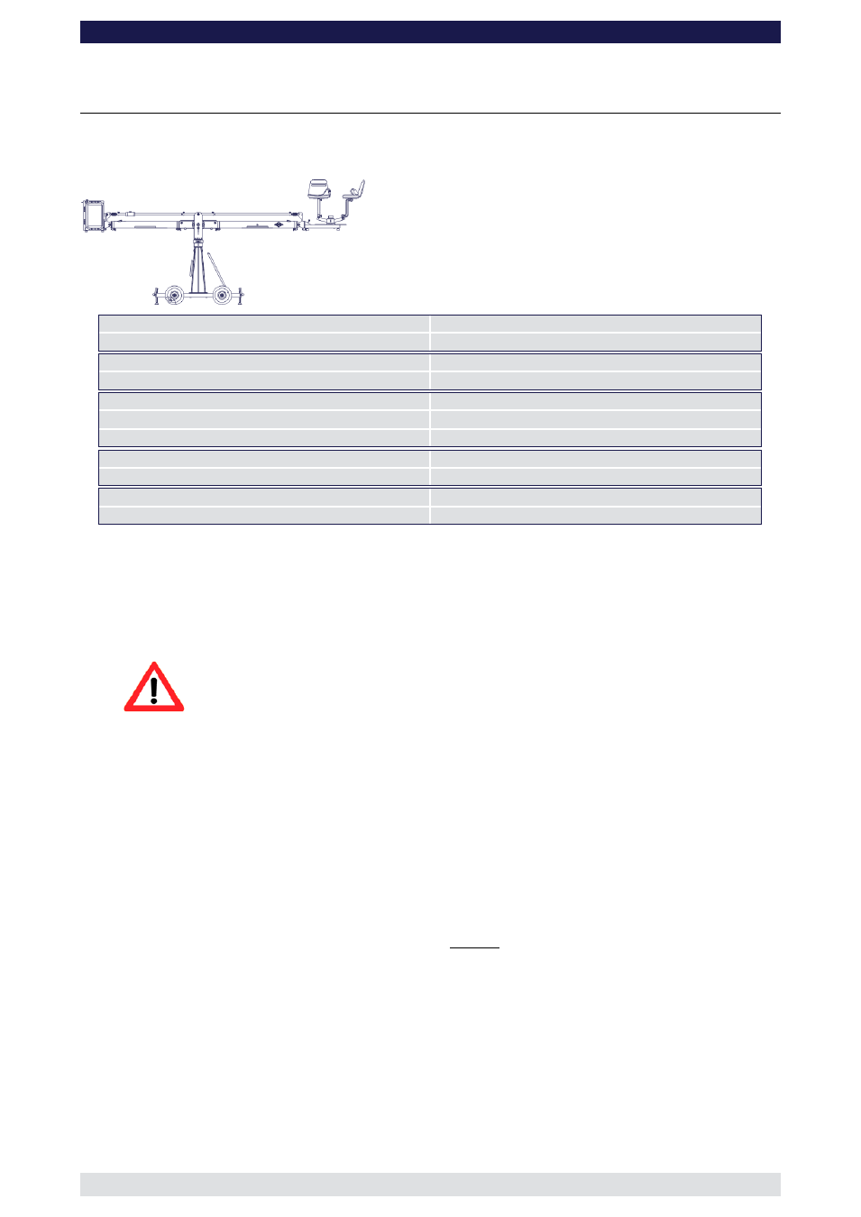
Version 1
(Pivot height 154cm / 5ft, Rear Extension 127cm / 4’ 2”)
Front extension arms required
1 x 150 cm / 5’
Rear extension arm required
1 x 127 cm / 4’ 2”
Lift range
319 cm / 10’ 5”
Maximum Euro-adapter height
331 cm / 10’ 10“
Lift capacity (working load) 2 pers. + accessories
250 kg / 550 lbs
Counterweight required for max. load
276 kg / 607 lbs
Counterweight required to balance empty arm
0 kg / 0 lbs
Crane weight (excluding dolly and weights)
149 kg / 327 lbs
Dolly weight
80 kg / 176 lbs
Arm reach (pivot to camera head mount)
253 cm / 8’ 3“
Length of rear end (pivot to outside of bucket)
220 cm / 7’ 2“
Continue from § 9, page 7
10. Connect one of the 150cm / 5’ sections to the middle section. Slip the connection
flanges into each other and secure them with the provided safety pin.
11. Connect the remaining angle adjuster to the end of the 150cm / 5’ section and secure
it with the provided safety pin.
Attention: Pinch point
12. Connect one of the 150cm / 5’ parallelogram rods to the middle section and the angle
adjuster and secure it with a safety pin at each end.
13. Connect the platform to the angle adjuster by inserting the male platform flange into
the female flange on the angle adjuster. Secure it with the safety pin.
14. Attach the weight bucket to the short end of the crane by inserting the male weight
bucket flange into the female flange on the angle adjuster. Secure it with the 2 safety
pins on the top of the angle adjuster.
Tip:
The angle adjuster has an integrated leveller. By turning it, the vertical plate
on the angle adjuster can be set to a perfect right angle. Correct setting of
the angle adjuster enhances the crane’s balance. Level the weight bucket,
the platform or the remote bracket before loading any weights.
Before operation, all locking pins, locking screws etc should be inspected to ensure
that all assembly sections are securely fastened.