Xten version 6 – Grip Factory Munich GF-8 User Manual
Page 35
GF-8 Xten Crane System Instruction Manual
Page: 34
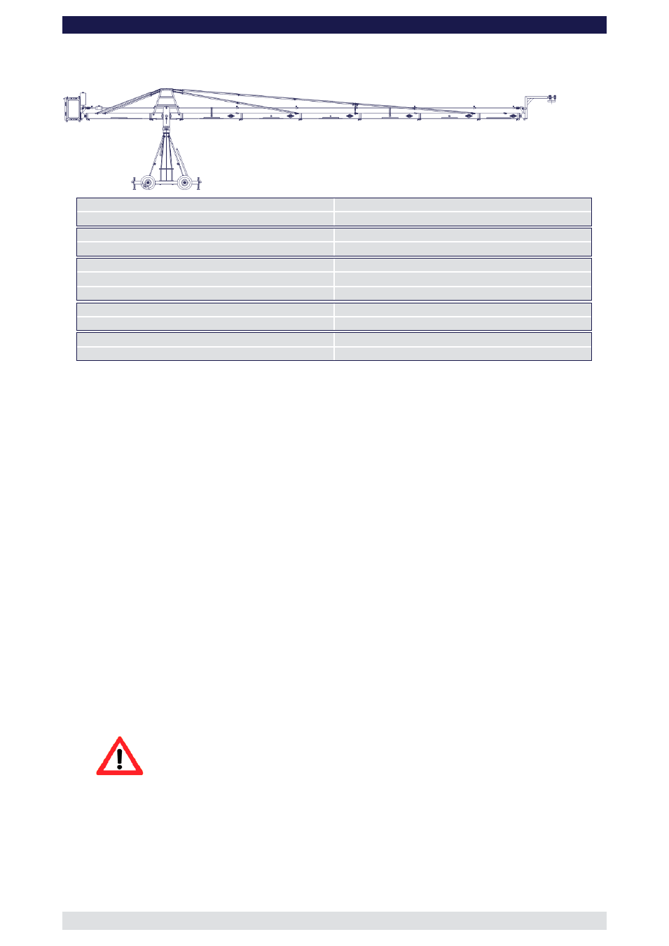
Xten Version 6
(Pivot height 184cm / 6ft, Large Rigging Harness, Rear Extension 160cm / 5’ 3")
Front extension arms required
5 x 150 cm / 5’ + 100 cm / 3’ 3”
Rear extension arm required
1 x 160 cm / 5’ 3”
Lift range
1462 cm / 47’ 9”
Maximum Euro-adapter height
950 cm / 31’ 2“
Lift capacity
70 kg / 154 lbs
Counterweight required for max. load
588 kg / 1293 lbs
Counterweight required to balance empty arm
266 kg / 585 lbs
Crane weight (excluding dolly and weights)
266 kg / 585 lbs
Dolly weight
80 kg / 176 lbs
Arm reach (pivot to camera head mount)
958 cm / 31’ 4“
Length of rear end (pivot to outside of bucket)
253 cm / 8’ 3“
Double rigging is required! Observe guidelines on page 43 and additionally ensure
that the Large Rigging Harness is used with double rigging to the rear and front.
Continue from § 9, page 7
10. Connect one of the 150cm / 5’ sections to the middle section. Slip the connection
flanges into each other and secure them with the provided safety pin.
11. Connect another 150cm / 5’ section to the first 150cm / 5’ section. Slip the connection
flanges into each other and secure them with the provided safety pin.
Note:
After each mounted section the support stand or rostrum can be moved up to
the next fixed section. We recommend to support longer crane versions with
more than one support stand or rostrum.
12. Now the lower front rigging system can be assembled. Therefor follow the instructions
as exemplary shown by version 7 and 8 on page 43.
13. After the lower front rigging system was assembled and connected to the connectors
of the second 150cm / 5’ section connect another three 150cm / 5’ sections and the
100cm / 3’ 3” section to the first ones. Slip the connection flanges into each other and
secure them with the provided safety pins.
Note:
After each mounted section the support stand or rostrum can be moved up to
the next fixed section. We recommend to support longer crane versions with
more than one support stand or rostrum.
14. Connect the remaining angle adjuster to the end of the 100cm / 3’ 3” section and
secure it with the provided safety pin.
Attention: Pinch point
15. Mount the parallelogram rod support to the respective section as shown on page 40.
16. Connect five 150cm / 5’ parallelogram rods and the 100cm / 3’ 3” rod to the middle
section and in turn to the angle adjuster and secure the connections with the provided
safety pins.
17. Connect the remote bracket to the angle adjuster by inserting the male remote
bracket flange into the female flange on the angle adjuster. Secure it with the safety
pin.
18. Attach the weight bucket to the short end of the crane by inserting the male weight