Top, front rigging – Grip Factory Munich GF-8 User Manual
Page 45
GF-8 Xten Crane System Instruction Manual
Page: 44
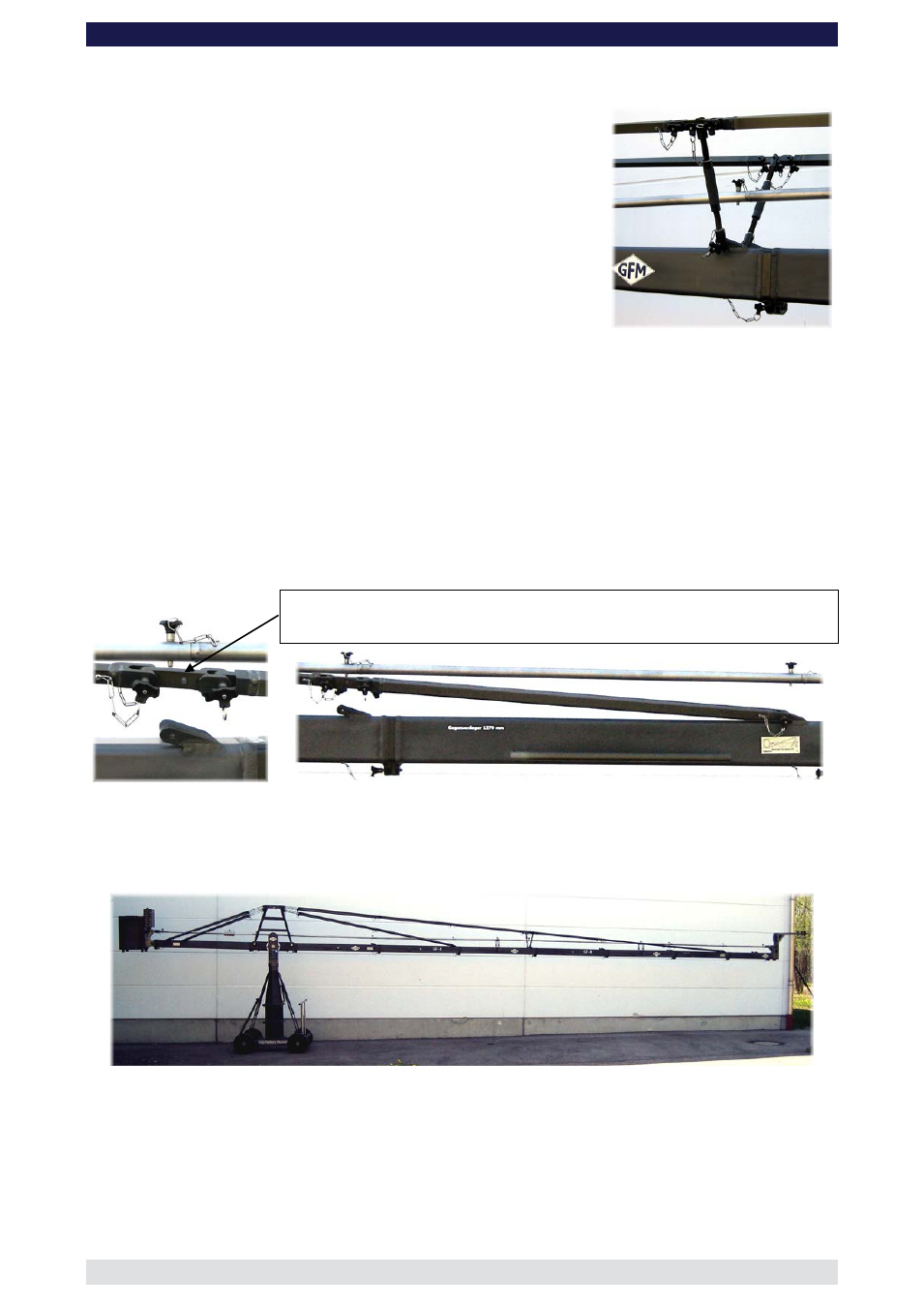
Top, front rigging
1.
Connect 3 x 142cm / 4’ 7” rigging rods to the turnbuckle
on the top front side of the large rigging harness. Ensure
that the locking pins are inserted fully.
2.
Connect a long Rigging Rod Connector to the third
Rigging Rod. In turn connect the Adjustable Rigging Rod
Support to the Rigging Connection on the third 150cm /
5ft arm section and then to the Rigging Rod Connector
ensuring that the locking pins are inserted fully.
Note:
This positioning applies to versions 5 to 8.
3.
Connect 2 x 142cm / 4’ 7” rigging rods to the long Rigging Rod Connector. Ensure
that the locking pins are inserted fully.
4.
Connect a short Rigging Rod Connector to the last 142cm / 4’ 7” rigging rod. Ensure
that the locking pin is inserted fully.
5.
Connect a 115cm / 3’ 9” rigging rod to the short Rigging Rod Connector and in turn to
the Rigging Rod Connection on the 127cm / 4ft arm section. Ensure that the locking
pins are inserted fully.
Attention:
The Rigging Rod Connectors should be positioned in the respective
versions as per the following instructions. Furthermore the rigging
must be assembled symmetrically by using the same length rods,
connectors etc in the same position on each side.
Short Rigging Rod Connector
6.
After the complete rigging system has been assembled, hand tighten the turnbuckles
until the rigging rods are taut. The turnbuckles can be secured with locking nuts.
Make sure that the rigging is absolutely straight. For this case the Adjustable Rigging
Rod Support has to be adjusted in a proper way.
Attention:
The rigging system of the crane arm should be hand tightened
symmetrically from both sides of the crane in a way that the arm is
absolutely straight when carrying the loads of the counterweight
bracket, the platform or remote bracket.