Version 2 – Grip Factory Munich GF-8 User Manual
Page 11
GF-8 Xten Crane System Instruction Manual
Page: 10
Version 2
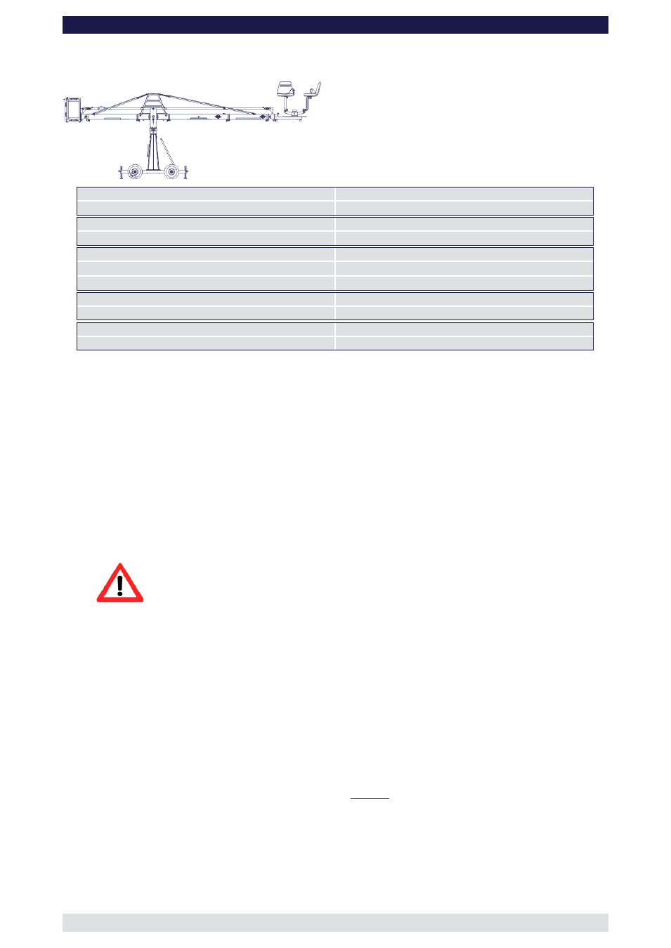
(Pivot height 154cm / 5ft, Standard Rigging Harness, Rear Extension 127cm / 4’ 2”)
Front extension arms required
1 x 150 cm / 5’ + 100 cm / 3’ 3”
Rear extension arm required
1 x 127 cm / 4’ 2”
Lift range
481 cm / 15’ 9”
Maximum Euro-adapter height
412 cm / 13’ 5“
Lift capacity (working load) 2 pers. + accessories
250 kg / 550 lbs
Counterweight required for max. load
456 kg / 1003 lbs
Counterweight required to balance empty arm
28 kg / 61 lbs
Crane weight (excluding dolly and weights)
173 kg / 380 lbs
Dolly weight
80 kg / 176 lbs
Arm reach (pivot to camera head mount)
351 cm / 11’ 5“
Length of rear end (pivot to outside of bucket)
220 cm / 7’ 2“
Rigging is required! Observe guidelines on page 41.
Continue from § 9, page 7
10. Connect one of the 150cm / 5’ sections to the middle section. Slip the connection
flanges into each other and secure them with the provided safety pin.
11. Connect the 100cm / 3’ 3” section to the 150cm / 5’ section. Slip the connection
flanges into each other and secure them with the provided safety pin.
Note:
After each mounted section the support stand or rostrum can be moved up to
the next fixed section. We recommend to support longer crane versions with
more than one support stand or rostrum.
12. Connect the remaining angle adjuster to the end of the 100cm / 3’ 3” section and
secure it with the provided safety pin.
Attention: Pinch point
13. Connect a 150cm / 5’ as well as a 100cm / 3’ 3” parallelogram rod to the middle
section and in turn to the angle adjuster and secure the connections with the provided
safety pins.
14. Connect the platform to the angle adjuster by inserting the male platform flange into
the female flange on the angle adjuster. Secure it with the safety pin.
15. Attach the weight bucket to the short end of the crane by inserting the male weight
bucket flange into the female flange on the angle adjuster. Secure it with the 2 safety
pins on the top of the angle adjuster.
Tip:
The angle adjuster has an integrated leveller. By turning it, the vertical plate
on the angle adjuster can be set to a perfect right angle. Correct setting of
the angle adjuster enhances the crane’s balance. Level the weight bucket,
the platform or the remote bracket before loading any weights.
16. Now the standard rigging system can be assembled. Therefor follow the instructions
as exemplary shown by version 17 and 18 on page 41.
Before operation, all locking pins, locking screws etc should be inspected to ensure
that all assembly sections are securely fastened.