D. input/output, E. data logger, C. clock/scheduler – Greenheck Microprocessor Controller (475595 IOM) TAP v2.10 April 2014 (RVE, ERCH-01, ERT-01) User Manual
Page 22
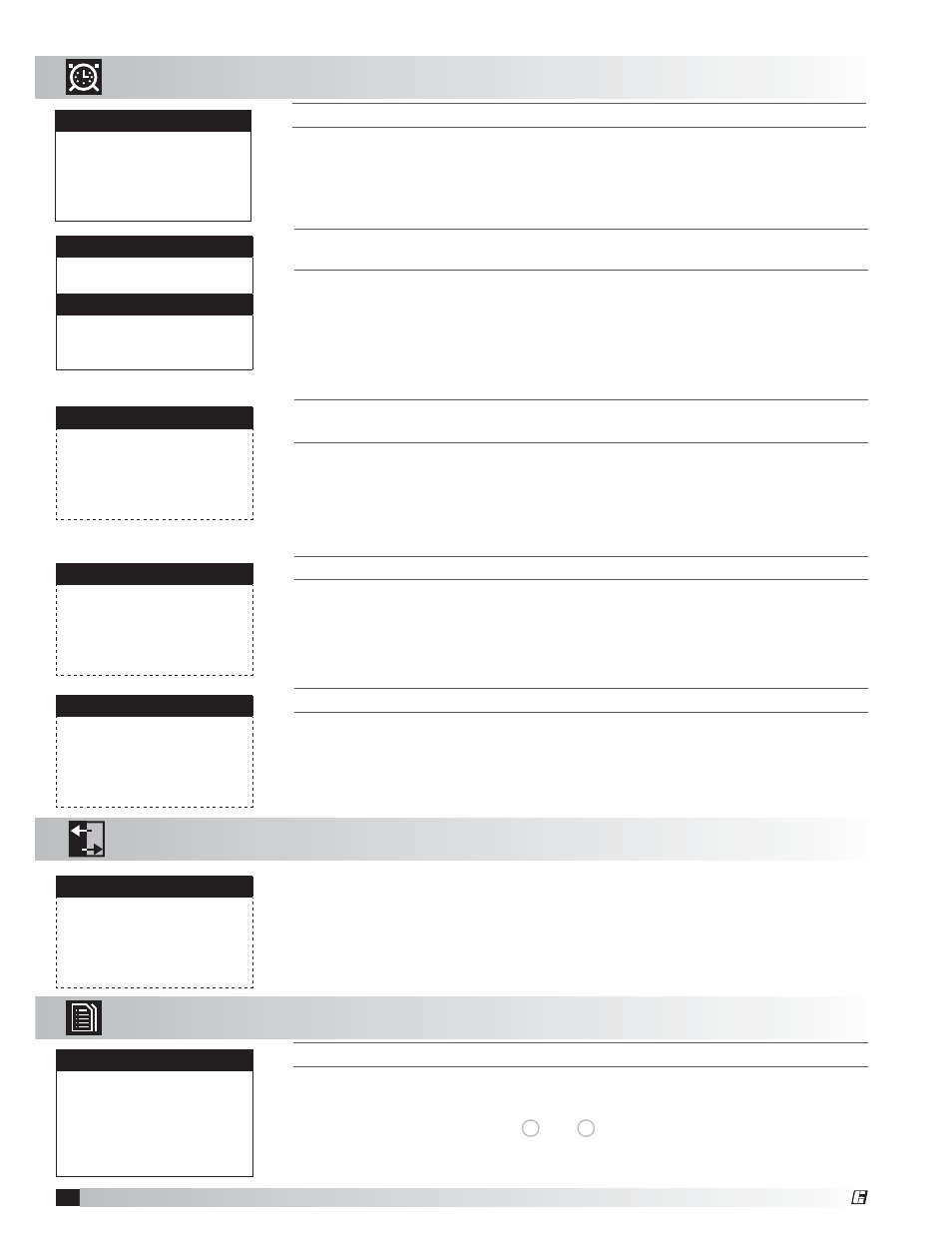
T
HIS
SCREEN
ALLOWS
THE
USER
TO
ADJUST
SCHEDULES
.
This screen only appears if a Schedule was added in the screen above.
The program supports up to seven separate schedules. Each schedule will
require the user to enter a Time On, Time Off and which days the schedule is
applicable for.
Scheduler
Schedule #:
#
Time On:
07:00
Time Off:
05:00
Days Enabled:
MTWTFSS
T
HIS
SCREEN
ALLOWS
THE
USER
TO
ENABLE
THE
MORNING
WARM
-
UP
SEQUENCE
AND
THE
DIFFERENTIAL
REQUIRED
TO
ALLOW
THE
SEQUENCE
TO
OCCUR
.
This screen only appears if Unoccupied Tempering is available.
The morning warm-up sequence calculates the time required to temper the space
to the occupied set point prior to occupancy. This sequence is limited between 10
to 60 minutes. The controller will re-evaluate the heating and cooling rate daily to
continually adjust to the changing climate.
Morning Warm-up
Morning Warmup Off
Temperature Diff:
2.0°F
T
HIS
SCREEN
ALLOWS
THE
USER
TO
SET
HOLIDAY
DATES
(
IF
ENABLED
).
This screen only appears if Holidays are enabled.
The internal time clock will go into unoccupied mode as long as the date is equal
to the holiday date (always a 24 hour period).
Holiday #1
Month: MM
Day: DD
Unoccupied for 24 hrs
T
HIS
SCREEN
ALLOWS
THE
USER
TO
ADD
THE
NUMBER
OF
U
NOCCUPIED
S
CHEDULES
AND
H
OLIDAYS
.
The Number of Schedules corresponds to the number of unoccupied periods the
user wishes to add. By setting the number of schedules to a value greater than
zero, the unoccupied mode will automatically be set to time clock.
A holiday is a single occurrence in which you would like the unit to be unoccupied
for 24 hours. A maximum of 15 holidays can be set. Holidays must be
reconfigured each year.
Scheduler
Number of schedules:
0
Holidays
Holiday = unoccupied mode
for 24 hours.
Number of Holidays:
0
To manually control I/O values, go to the Service menu > Overrides.
Similar screens appear for all controller inputs and outputs.
Your controller may not utilize all equipped of the inputs and outputs
shown. See unit wiring diagram for your specific configuration.
Analog Input
Outside Temperature
Input B01:
75.0°F
D. Input/Output
The Input/Output menu allows the user to quickly view the status of the controller
inputs and outputs.
E. Data
Logger
T
HIS
SCREEN
IS
AN
EXAMPLE
OF
A
RECORDED
ALARM
.
The unit conditions are displayed for past alarm events. The date, time,
temperatures and unit status are recorded.
To clear recorded alarms, press
Prg
and
Esc
simultaneously.
13:21:04 MM/DD/YY
OA TEMP SENSOR
Outside Air T:
-623.3
Discharge T:
52.8
Cold Coil T:
55.9
Room T:
72.5
SYS ON-HEATING
The Data Logger menu allows the user to view up to 100 past alarms.
C. Clock/Scheduler
The Clock/Scheduler menu allows the user to view and alter the time and date.
The user can also add up to seven schedules for occupancy requirements.
T
HE
C
LOCK
SCREEN
ALLOWS
THE
USER
TO
ADJUST
THE
TIME
AND
DATE
.
Set Date & Time
Day: Monday
Date: MM/DD/YY
Hour: 15:30
22
DDC Controller for Tempered Air Products
®