A. printing and data transfer, Printing and data transfer, Appendix a – Fluke Biomedical 2MF Index User Manual
Page 89: Introduction
A-1
Appendix A
Printing and Data Transfer
Introduction
This Appendix provides information on the Simulator’s RS232 and printer ports,
including how to configure the port on your printer or computer.
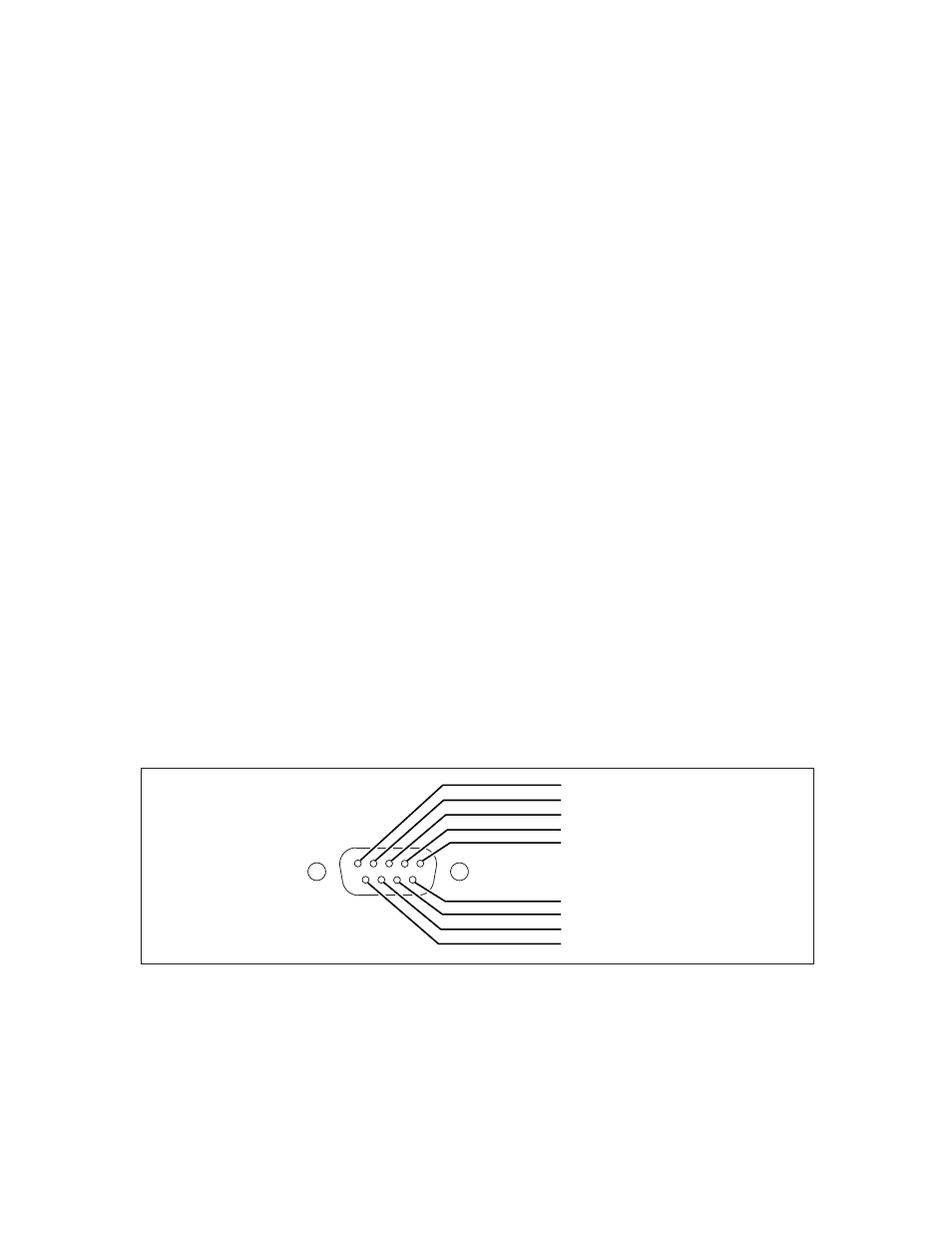
The Simulator provides a male D (9-pin) bi-directional serial port located at the back side
of the unit, for the transfer of data to a computer or printer, and for computer control of
the Simulator. The Data Computer Equipment (DCE) wiring configuration is shown
Figure A-1.
Index 2MF RS232 Configuration
Fluke Biomedical offers a bi-directional serial null modem cable for connect the
Simulator to your computer (IBM compatible) or serial printer. Please specify Fluke
Biomedical Part Number 2238626 when ordering.
1- C-Lock
2- TX
3- RX
4- DTR/DSR
5- Ground
6- DTR/DSR
7- RTS/CTS
8- RTS/CTS
9- Unused
esl165.eps
Figure A-1. Male D Cable End
C-Lock
Pin 1 of the serial connector provides the Simulator’s synchronized pulse. This pulse is
normally in phase with the start of each 64-point pleth wave. The phase of the sync pulse
with regard to the wave can be varied using the [CPHASE nn] command, where nn is a
number in the range of 0 to 63. The pulse is a negative going attenuated logic level. For
more information, refer to “Appendix E: Computer Control”.