Fluke Biomedical 2MF Index User Manual
Page 120
Index 2MF
Users Guide
G-8
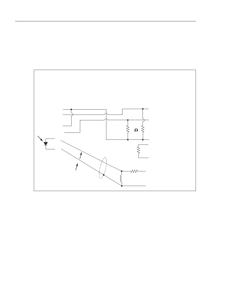
In some cases, it may be advantageous to not use the floating diode source. In these
cases, the Simulator provides a ground pin at pin 9, and both positive and negative
simulation voltage signals on pins 7 and 8. These may be converted to current signals by
appropriate scaling resistors as noted in Figure G-5.
Normally, oximeter shield pins should not be tied to the Simulator ground, but there may
be exceptions. Again, only a thorough study and understanding of the oximeter interface
circuits can answer these questions.
EXAMPLE: OHMEDA HARDWIRE CABLE
INDEX 2
PIN
OHMEDA PROBE
PIN
TO OXIMETER
IR CATHODE
R CATHODE
RED ANODE
15.8
ID RES
ID RES COMMON
DET. ANODE
SHLD/DET RET
T
1
2
3
4
5
6
7
8
9
1
2
3
4
5
6
7
8
9
X2
56K
1%
200K, 1%
100K, 1%
esl163.eps
Figure G-5. Example: Ohmeda Hardware Cable