Fluke Biomedical 2MF Index User Manual
Page 21
Blood Oxygen and Pulse Oximeters
Pulse Oximeters
2
2-3
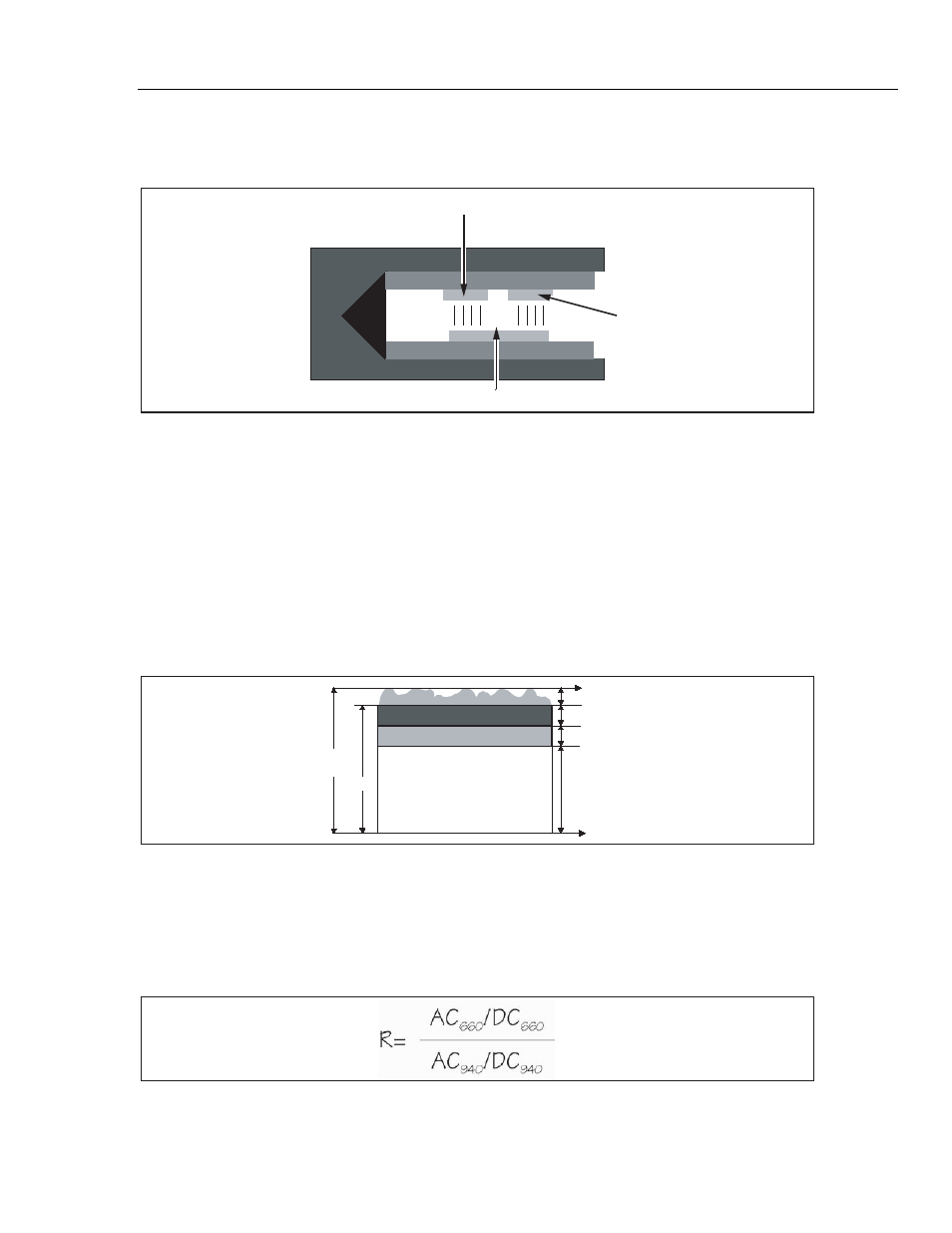
Figure 2-3 shows a typical pulse oximeter configuration, noting the location of the red
and infrared LED's.
940nm Infrared LED
660nm Red LED
Photosensor
esl005.eps
Figure 2-3. Diagram of Sample Finger Probe for a Typical Pulse Oximeter
Using this dual light emitting and sensing technology, the pulse oximeter determines the
amount of light absorbed by the blood and calculates the percent of oxygen saturation
(SaO2).
However, it is not quite that simple. Pulse oximeters must also calculate out the effect of
absorption caused by the presence of venous and capillary blood and soft tissue in order
to obtain the true SaO2 value. To do so, pulse oximeters use a system that distinguishes
between “AC" components (the pulsating arterial blood) and “DC" components (the non-
pulsating components mentioned just above).
Figure 2-4 shows the different AC and DC components graphically.
DC
AC
Light
Absorption
Absorption due to pulse
Capillary blood
esl006.eps
Figure 2-4. Diagram of Light Absorbers in Tissue
The pulse oximeter determines the AC component of absorbency at each wavelength and
divides this by the corresponding DC (amplitude) component. This results in a "pulse-
added" absorbency that is independent of the light intensity. The ratio (R) of these pulse-
added absorbances is calculated using the formula shown in Figure 2-5.
esl007.eps
Figure 2-5. AC/DC Infrared and Red Absorption Ratio
When the ratio of red-to-infrared absorbance equals 1.00, the saturation is approximately 81%.