Fluke Biomedical ESA615 User Manual
Page 37
Electrical Safety Analyzer
How to Do Electrical Safety Tests
23
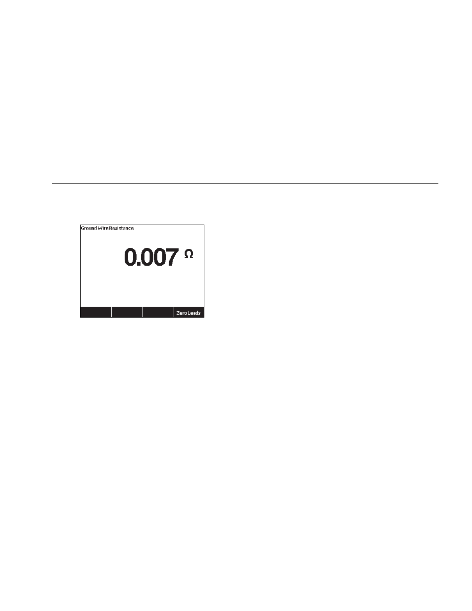
7. After you make the connections to the DUT, the
measured resistance shows in the display. See
Figure .
gtv105.jpg
Figure 11. DUT Ground Resistance Measurement
Warning
To prevent electrical shock, remove the null
post adapter from the
∅
/Null jack after a test
lead zero is performed. The
∅
/Null jack
becomes potentially hazardous during some
of the test conditions.
A low resistance measurement is necessary to make sure
there is a good ground connection through the power
cord. Refer to the applicable electrical safety standard for
the specified limit value to be followed.
Figure shows the electrical connections between the
Product and the DUT. Table 4 is a list of the abbreviations
used in the schematics and their descriptions.