1 removal – Flowserve MX Limitorque User Manual
Page 138
Limitorque MX Maintenance and Spare Parts FCD LMENIM2314-00 – 07/08
130
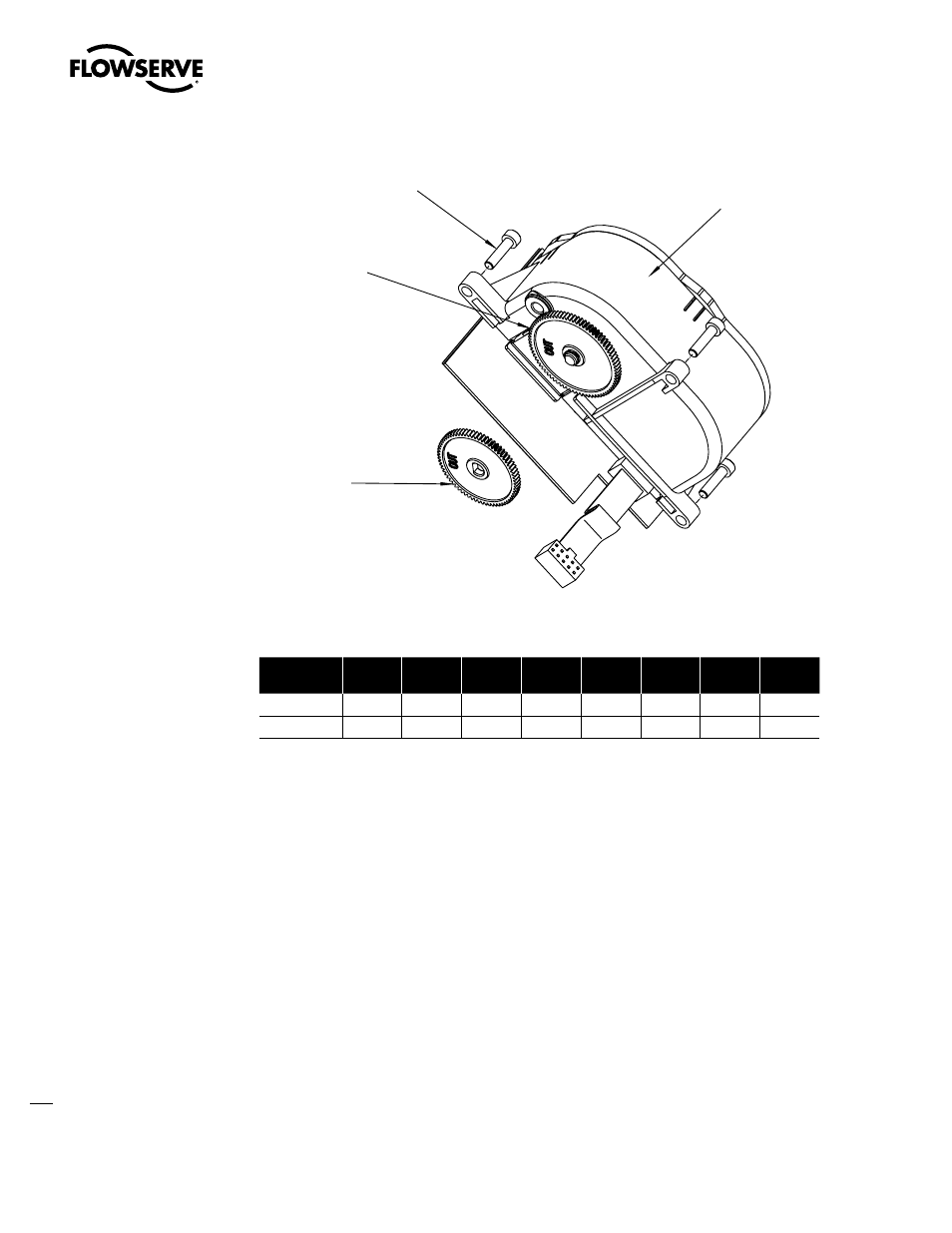
Figure 5.16 – Encoder
.9VOJUTXJUI%SJWF
4QFFE*%PSSFRVJSF
PQUJPOBMJOQVUHFBS
3FGFSFODFUBCMFCFMPX
UPEFUFSNJOFZPVSBDUVBUPS
SFRVJSFNFOUT
.9VOJUTXJUI%SJWF
4QFFE*%UISVSFRVJSF
TUBOEBSEJOQVUHFBS
3FGFSFODFUBCMFCFMPX
UPEFUFSNJOFZPVSBDUVBUPS
SFRVJSFNFOUT
Table 5.11 – Encoder Drive Sleeve Speed (RPM)
Drive Sleeve
Speed ID
1
2
3
4
5
6
7
8
50 Hz
15
22
33
43
65
84/110
1
127/143
1
165
2
60 Hz
18
26
40
52
77
100/131
1
155/170
1
200
2
1: MX-85, -140, and -150 only.
2: N/A MX-85, -140, and -150.
NOTE: MX units with Drive Speed ID 1 or 2 require an optional input gear. Reference the Output RPM block located
on the MX nameplate and cross-reference in table above to determine the unit Drive Speed ID.
5.13.1 Removal
NOTE: Before removal you must:
a
CAUTION: Potential to cause electrostatic damage to electronic components. Before handling
electronic components, ensure that you are discharged of static electricity by briefly touching a
grounded metal object.
1. Remove the control panel (subassembly #7). (See Section 5.1.)
2. Remove the control module (subassembly #8). (See Section 5.2.1.)
NOTE: The encoder is a sealed assembly of high-precision components and not suitable for repair.
Should the encoder fail, it will be necessary to install a factory replacement.