Combustion basics – Fieldpiece HG2 - HVAC Guide System Analyzer User Manual
Page 34
66
WWW.FIELDPIECE.COM WWW.FIELDPIECE.COM WWW.FIELDPIECE.COM WWW.FIELDPIECE.COM WWW.FIELDPIECE.COM WWW.FIIELDPIECE.COM WWW.FIELDPIECE.COM WWW.FIELDPIECE.COM WWW.FIELDPIECE.COM WWW.FIELDPIECE.COM WWW.FIELDPIECE.CO
Combustion Basics
Combustion is the rapid oxidation of fuel. Oxygen
from air (20.9% oxygen & 79.1% Nitrogen) is used to
burn fuel producing heat. Th
e appliances installed and
serviced by technicians, rely on clean effi
cient fl ames to
produce the energy needed to heat homes and hot water
etc. Combustion testing is necessary to maximize the ef-
fi ciency of the combustion systems and to minimize the
harmful emissions produced. Carbon monoxide and
carbon dioxide (greenhouse gas emissions) are products
of combustion. Proper tuning of the combustion pro-
cess by combustion testing will reduce the production
of harmful carbon monoxide and decrease the amount
of fuel burned through the increase in effi
ciency.
Combustion effi
ciency can typically be increased by
creating a more balanced Air to Fuel ratio. Th
e ratio of
air to fuel determines how much CO
2
is produced and
how effi
cient the fl ame is.
Tuning of the O
2
, CO
2
excess air, stack temperature
and temperature rise to match the appliance manufac-
turers specifi cations will increase the effi
ciency and help
to maximize the performance and life expectancy of the
equipment.
A properly tuned atmospheric natural gas or pro-
pane fi red appliance will have approximately 6 to 9% O
2
in the fl ue gases. Fuel oil appliances with fl ame retention
burners will have approximately 3 to 7% O
2
in the fl ue
gases. For a more detailed breakdown see the chart on
page 32.
Testing and adjustment to the combustion process
ensures that the highest combustion effi
ciency is safely
achieved, thereby reducing the overall amount of fuel
used in producing the energy needed. It is still necessary
to test and adjust the appliance to the manufacturers’
specifi cation for airfl ow in the duct system, temperature
rise across the heat exchanger and anything else that
may need testing. Testing and balancing of appliances
to meet manufacturers’ specifi cations helps to ensure
maximum system effi
ciency and equipment longevity.
5
Combustion testing does not take into account start
up losses, standby losses, cabinet/boiler body losses, or
distribution losses in ducts or piping.
5 Content adapted from Erik Rasmussen's book Combustion Analysis and Fuel
Effi ciency
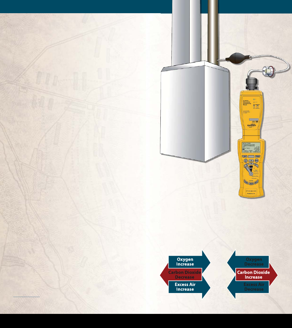
Figure 34. Entering the CO measurement for the Combustion Test us
ing an ACM3 Carbon Monoxide Head and the pump that's included
with the AOX2 Combustion Check Head.
Below is Fig 4-9 from the book Combustion Analy-
sis and Fuel Effi
ciency, Erik Rasmussen ESCO Press
2007.
Supply
Supply
Plenum
Plenum
Flue
Flue