Fieldpiece SC77 - True RMS Clamp Meter User Manual
Maintenance, Symbols used, For your safety
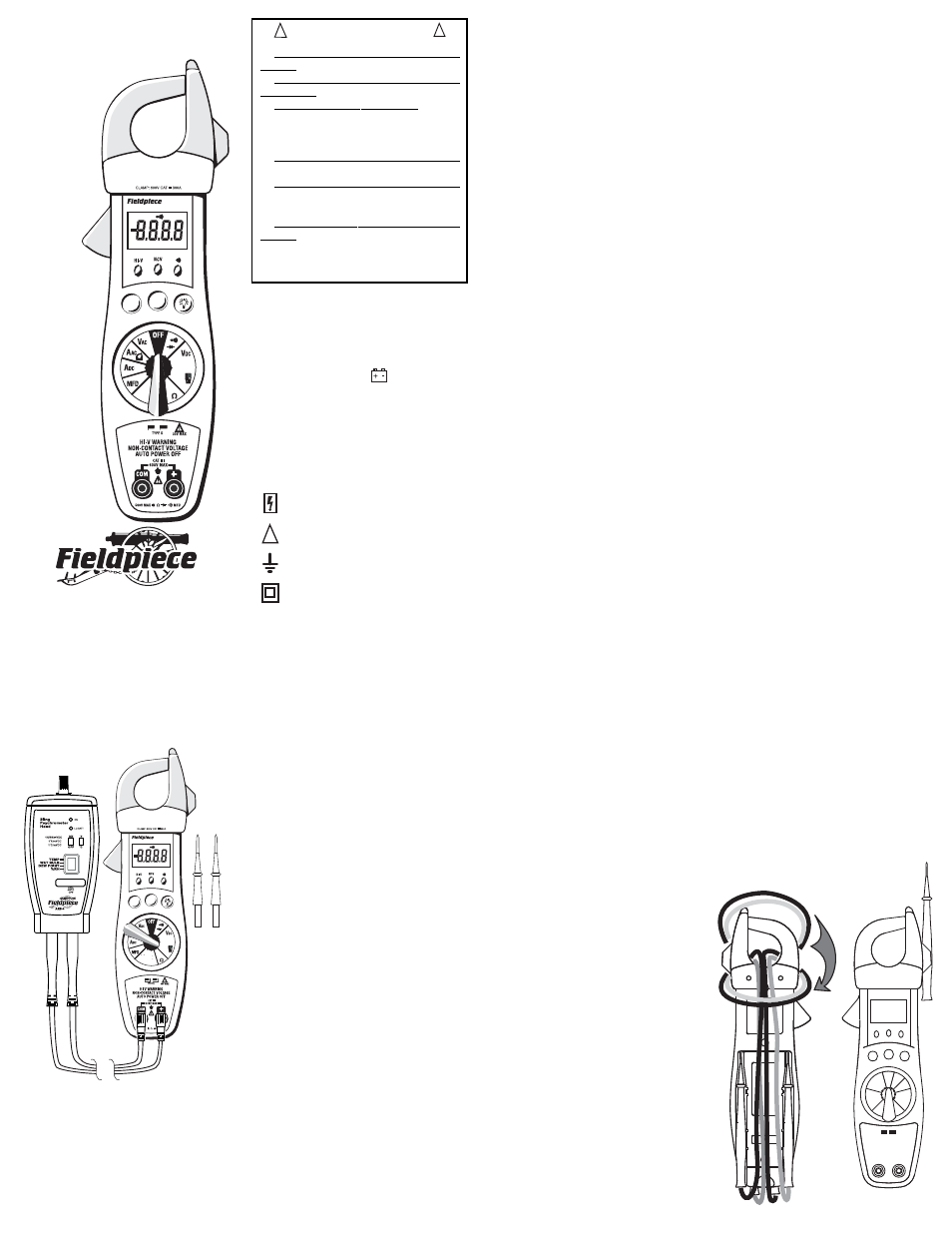
Maintenance
Clean the exterior with clean dry
cloth. Do not use liquid.
Battery replacement:
When the
multimeter displays " " the battery
must be replaced. Disconnect and
unplug leads, turn meter off, and
remove the battery cover. Replace the
battery with a NEDA type 1604 9V bat-
tery.
Symbols used:
Caution, risk of electric shock
Caution, refer to manual.
Ground
Double insulation
For your safety...
General:
Disconnect the test leads
before opening the case. Inspect the
test leads for damage to the insulation
or exposed metal. Replace if suspect.
Never ground yourself when taking
electrical measurements. Do not touch
exposed metal pipes, outlets, fixtures,
etc., which might be at ground poten-
tial. Keep your body isolated from
ground by using dry clothing, rubber
shoes, rubber mats, or any approved
insulating material. When disconnect-
ing from a circuit, disconnect the
"RED" lead first, then the common
lead. Work with others. Use one hand
for testing. Turn off power to the circuit
under test before cutting, unsoldering,
or breaking the circuit. Keep your fin-
gers behind the finger guards on the
probes. Do not measure resistance
when circuit is powered. Do not apply
more than rated voltage between input
and ground.
All voltage tests:
For model SC77
all voltage ranges will withstand up to
600VDC or 600VAC rms. Do not apply
more than 600VDC or 600VAC rms.
AC tests:
Disconnect the meter
from the circuit before turning any
inductor off, including motors, trans-
formers, and solenoids. High voltage
transients can damage the meter
beyond repair. Do not use during elec-
trical storms.
Limited warranty
This meter is warranted against
defects in material or workmanship for
one years from date of purchase.
Fieldpiece will replace or repair the
defective unit, at its option, subject to
verification of the defect.
This warranty does not apply to
defects resulting from abuse, neglect,
accident, unauthorized repair, alter-
ation, or unreasonable use of the
instrument.
Any implied warranties arising from
the sale of a Fieldpiece product,
including but not limited to implied war-
ranties of merchantability and fitness
for a particular purpose, are limited to
the above. Fieldpiece shall not be
liable for loss of use of the instrument
or other incidental or consequential
damages, expenses, or economic loss,
or for any claim of such damage,
expenses, or economic loss.
State laws vary. The above limita-
tions or exclusions may not apply to
you.
Obtaining service
Return any defective SC77 to
Fieldpiece for service. For warranty
service, please provide a proof of pur-
chase. Contact Fieldpiece for out of
warranty repair charges. Contact infor-
mation can be found at our website
www.fieldpiece.com.
OPERATOR’S MANUAL
400
DISCONNECT
TEST LEADS
340
SC77
µ
Auto
4000m
400m
HOLD
NCV
m A K M Ω
m V V
APO HOLD n m m F
AC
DC
Works with
Fieldpiece
accessory
heads!
AUTO RANGING T-RMS
DIGITAL CLAMP METER
Model SC77
WARNINGS
DISCONNECT AND UNPLUG TEST
LEADS before opening case.
TEST NCV FUNCTION ON KNOWN
LIVE WIRE before using.
DO NOT APPLY VOLTAGE greater
than 30VAC or 60VDC to the thermocou-
ple or the jacks when the rotary dial is on
°F.
REMOVE THE THERMOCOUPLE
when taking voltage measurements.
DISCONNECT THE TEST LEADS
when taking temperature measure-
ments.
DO NOT APPLY VOLTAGE TO THE
JACKS when the rotary dial is on
microamps. Even low voltages can cause
a current overload and potentially dam-
age the circuit.
!
!
Works with Fieldpiece
accessory heads
Connect your Fieldpiece accessory
head to SC series meter through
included deluxe silicone leads. Use
400mVDC or 4000mVDC range for
most heads.
SC77 connected to
ARH4 through leads.
Available Fieldpiece
accessory heads
There is a Fieldpiece accessory
head available for just about any job.
There are heads to measure tempera-
ture, superheat, subcooling, RH%, wet
bulb, dew point, vacuum (microns of
mercury), manometer (inches of water
column), amps AC&DC, high voltage,
CO, CO2, air velocity, and many more.
Non-contact voltage
With the NCV tab on the tip of the
clamp close to an AC voltage, press
the NCV button. The NCV LED will
light and the beeper will beep. The
NCV function is sensitive enough to
detect 24VAC on thermostats.
Hi voltage indicator
In any VAC/VDC range, when you
touch a voltage greater than 30V, the
beeper will beep and the red Hi-V LED
will blink. BE CAREFUL!
Current measurements
The fixed jaw is longer than the
moveable jaw to make it easier to
select just one wire from a bundle.
With the jaws closed, separate one
wire using the long fixed jaw. Slide it to
the corner where the two jaws meet.
Then open the jaws to let it in. You can
select the wire without having to hold
the jaws open.
Microamps
For measuring the flame diode cur-
rent in a heater control.
Capacitance
For motor-start and motor-run
capacitors. Disconnect the capacitor
from power first. Short the terminals to
discharge the capacitors. Disconnect
any resistors that might be between
the terminals of the capacitor. The
SC77 displays a “dsc” symbol when
capacitor needs discharging.
Temperature
Plug any K-type thermocouple
directly into the meter to measure tem-
perature. Temperature measurement
will maintain good accuracy in fast
changing environments. One thermo-
couple is included. No adapter is
required.
Field Temp. calibration
For accuracies of ±1° calibrate the
SC77 to a known temperature. A glass
of stabilized ice water is very close to
32°F (0°C) and is usually very conven-
ient.
1. Select the °F range on the SC77.
2. Remove back case. Hold the bat-
tery in place with a rubber band.
3. Stabilize a large cup of ice water by
stirring.
4. Immerse the probe and let it stabi-
lize. Continue stirring.
5. Adjust VR3 (lower right corner of
PCB) to get close to 32°F (0°C)
then adjust VR4 (below VR3) to get
within 0.1°F/C of 32°F (0°C).
6. To calibrate in °C, close the jumper
that is to the left of VR3.
Display ºC or ºF
Remove back of meter, locate
jumper on lower right corner of PCB
(just below VR3) and close jumper to
read temperature in °C.
Using &storing test leads
Because the wire insulation is sili-
cone they will stay flexible in cold
weather and will not melt if bumped by
a soldering iron.
Use the single test probe holder on
clamp to make voltage testing easy.
For convenient lead storage, wrap
the leads as shown.
400
DISCONNECT
TEST LEADS
1000
SC77
µ
Auto
4000m
400m
HOLD
NCV
F C
TEMP
400
F
C
m A K M Ω
m V V
APO HOLD n m m F
AC
DC
!