DNF Controls Universal Switch Panel (USP-8, USP-8D, & USP-16) User Manual
Page 6
4 OF 41 Universal Switch Panel (USP) User Manual
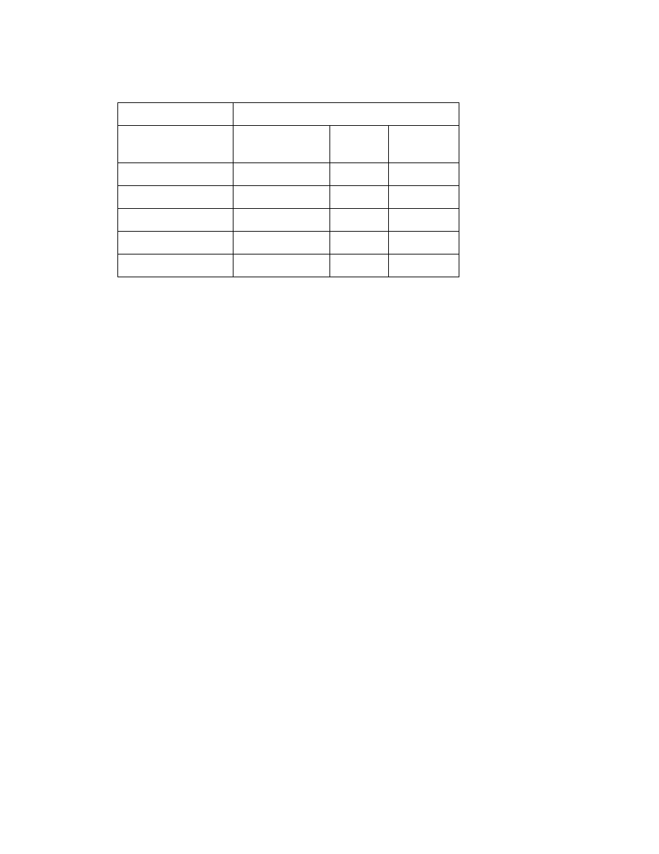
I. UNIVERSAL SWITCH PANEL MODEL NUMBERS
Model Number
Number of:
Front Panel
Switches
GPI
GPO
USP-8
8
8
8
USP-8A
8
16
16
USP-16
16
16
16
USP-EM-8
None
8
8
USP-EM-16
None
16
16
II. OPERATION OVERVIEW
The Universal Switch Panel (USP) is a panel of generic switches designed to emulate
the operation of mechanical switches. The mechanical switch feel is provided by the
USP’s front panel switch. The mechanical switch’s contact closure is provided by the
USP’s general purpose outputs (GPO). The mechanical switch’s internal tally
indicator is provided by the USP switch’s backlight.
Unlike mechanical switches, the operating mode of the front panel switches, GPO
contact closures, and tally can be easily configured by the user for their specific
application. Additionally, ON text and OFF text can be displayed on the face of the
USP switch. Each switch can be configured to operate standalone or as part of a
radio group. Also, each GPO contact closure can be configured to operate as
Momentary, Latching, or interlocked (commonly referred to as “radio group”). And,
each tally can be configured to be Always ON, Always OFF, follow the state of the
contact closure, or follow the state of an external device. Additionally, the ON and
OFF tally for each tally can be individually configured to be Dark, Red, Green, or
Amber, and Flash or not.
Unlike a mechanical switch, a switch on the Universal Switch Panel can be configured
to control a GPO on another USP, turn it ON and OFF.
A. FRONT PANEL SWITCH
Pressing a switch causes its associated GPO to turn ON or turn OFF. The switch
contacts, represented by the GPO, operate according to the user configured GPO
operating mode. The switch can control a GPO located on the same panel or it
can control a GPO located on another, remote, USP.
Each switch used on the USP front panel has an LCD display mounted on its face.
The display is used to show an ON tally text label and an OFF tally text label.
Each switch display can be configured by the user to show 1 row of 3 characters,
2 rows of 4 characters each, or 3 rows of 6 characters each. The display
backlight functions as the tally, replacing an internal bulb or led. The user can
individually configure each backlight to turn red, green, amber, or dark to show
an ON or OFF tally. Additionally, the backlight can be configured to flash in its
ON or OFF tally state.