Edit station, 6 six or seven-digit clock setup, Six or seven-digit clock setup – Daktronics Track & Field Interfaces User Manual
Page 14
8
FinishLynx Photo Finish System
Edit Station
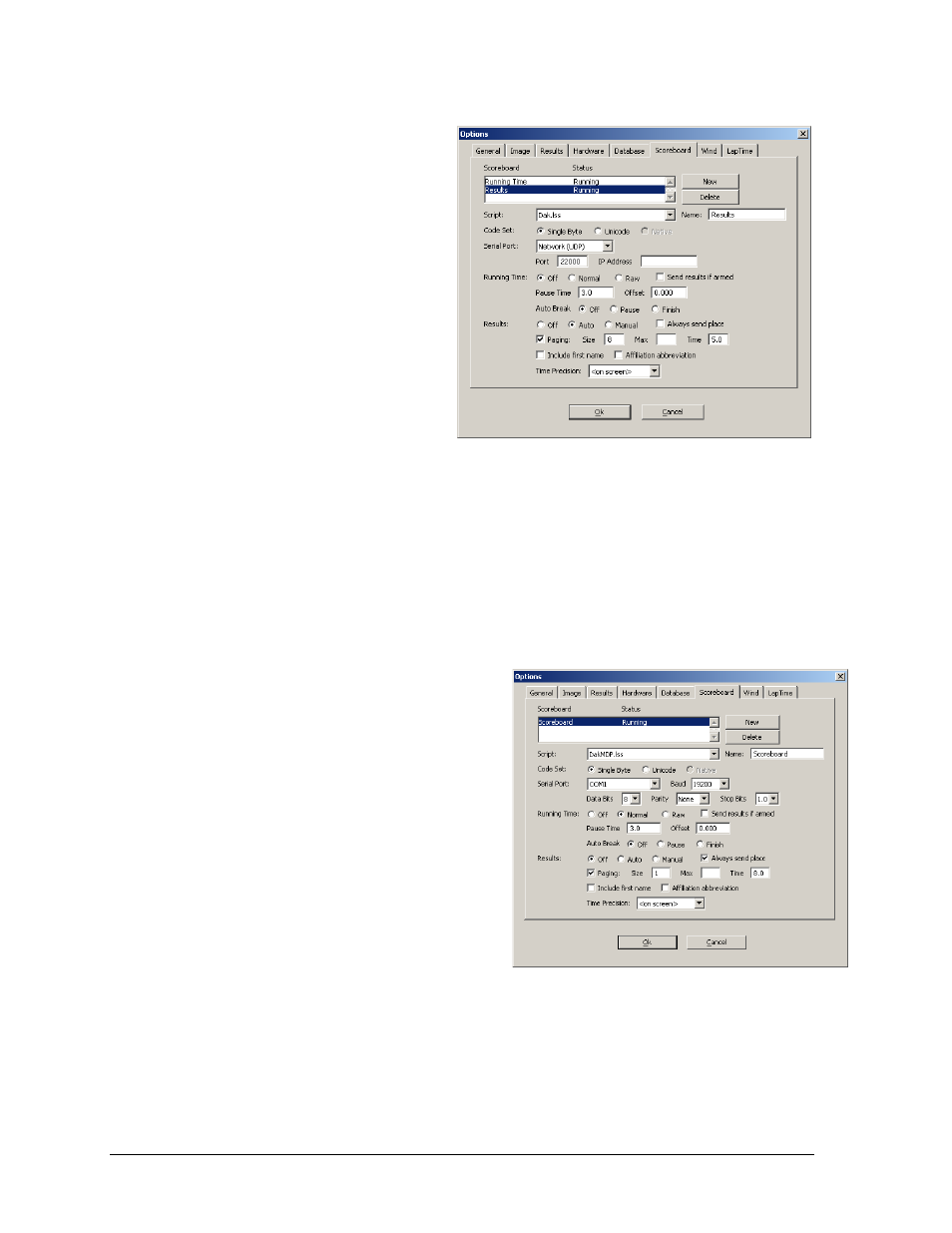
Set up the Edit Station options the
FinishLynx computer as follows
(refer also to Figure 10):
Script: “Dak.lss”
Name: “Results”
Code Set: Single Byte
Serial Port: Network (UDP)
Port “22000”
Running Time: Off
Auto Break: Off
Results: Auto
Paging enabled; set the Size to
the number of lanes that can be
displayed on the matrix
display; Time “5.0”
2.6 Six or Seven-Digit Clock Setup
Reference Drawings:
TI-2020 or TI-2021 with FinishLynx ..................................................... Drawing A-267638
In this setup, the display typically sets on the infield near the finish. The display can be
controlled via a serial port on the capture computer or the on the Lynx connection box.
1. Identify which serial port will control
the display.
2. Connect the signal converter kit (part #
0A-1125-0007) to a serial port from
FinishLynx to the input jack on the
display. The cabling and configurations
should go according to Drawing A-
267638.
3. Set up the scoreboard options on the
FinishLynx computer as follows (refer
also to Figure 11):
Script: “DakMDP.lss”
Name: “Scoreboard”
Code Set: Single Byte
Serial Port: Select an available COM port.
Note: If connecting to the serial port on the connection box, select Camera.
Baud: 9600
Data Bits: 8
Parity: None
Figure 10: Edit Station Options for Venus/V-Play Via UDP/IP
Figure 11: Scoreboard Options for 6 or 7-Digit Clock