Daktronics Track & Field Interfaces User Manual
Page 11
FinishLynx Photo Finish System
5
If a USB-to-Serial adapter is being
used on the FinishLynx computer,
use code 8602 on the All Sport 5000.
For an All Sport 4000, use codes 45,
46, or 47 depending on the
scoreboard used (refer to Appendix B
of the All Sport 4000 operations
manual, ED-9999).
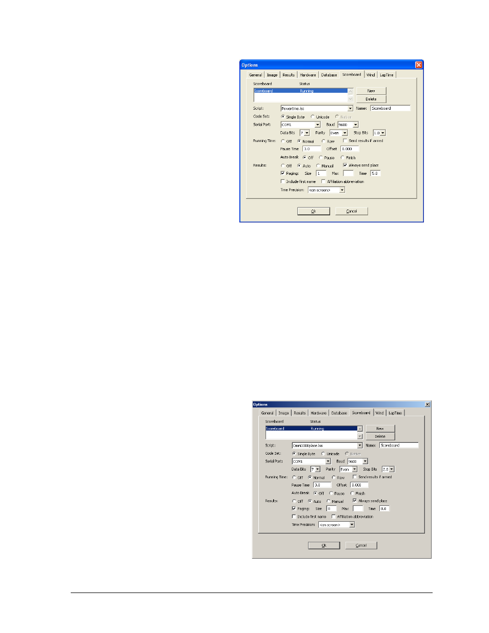
Set up the scoreboard options on the
FinishLynx computer as follows
(refer also to Figure 5):
Script: “Powertime.lss”
Name: “Scoreboard”
Code Set: Single Byte
Serial Port: Select an
available COM port.
Baud: 9600
Data Bits: 7
Parity: Even
Stop Bits: 1.0
Running Time: Normal
Auto Break: Off
Results: Auto, Always send place enabled
Paging enabled, Size “1”, Time “5.0”
2.3 Signal Converter Setup for a Lane/Place/Time Scoreboard
Reference Drawings:
Track SCBD w/ FinishLynx, in Press Box ........................................... Drawing A-104300
For scoreboard installation, address
plug, and protocol plug settings, refer to
the LED Aquatic/Track Displays SW-
2000 Series Display Manual (ED-12156).
Set the address plugs and protocol plugs
according to the FinishLynx scoreboard
settings in Section 3 of ED-12156. The
cabling should go according to Drawing
A-104300.
Set up the scoreboard options on the
FinishLynx computer as follows (also
refer to Figure 6):
Script: “Omni1000place.lss”
Name: “Scoreboard”
Code Set: Single Byte
Serial Port: Select an available COM port.
Figure 5: Scoreboard Options for USB-to-Serial Adapter
Figure 6: Scoreboard Options for Lane/Place/Time