Daktronics Track & Field Interfaces User Manual
Page 12
6
FinishLynx Photo Finish System
Baud: 9600
Data Bits: 7
Parity: Even
Stop Bits: 2.0
Running Time: Normal
Auto Break: Off
Results: Auto, Always send place enabled
Paging enabled; set the Size to the number of lanes that can be displayed on the
scoreboard (ex, 4 for a four line scoreboard).
2.4 DMP-7000 (Venus 7000) or V-Play Controller Setup Via Serial
Reference Drawings:
System Riser: F.Lynx/Hytek/Venus Via Comm Ports .......................... Drawing B-127739
In this setup, RTD (Real Time Data) is
sent from the FinishLynx system to the
DMP-7000 (Venus 7000) or V-Play
controller via serial port. The cabling
should go according to Drawing
B-127739.
If an All Sport 5000 is used, enter code
8604.
Set up the scoreboard options on the
FinishLynx computer as follows
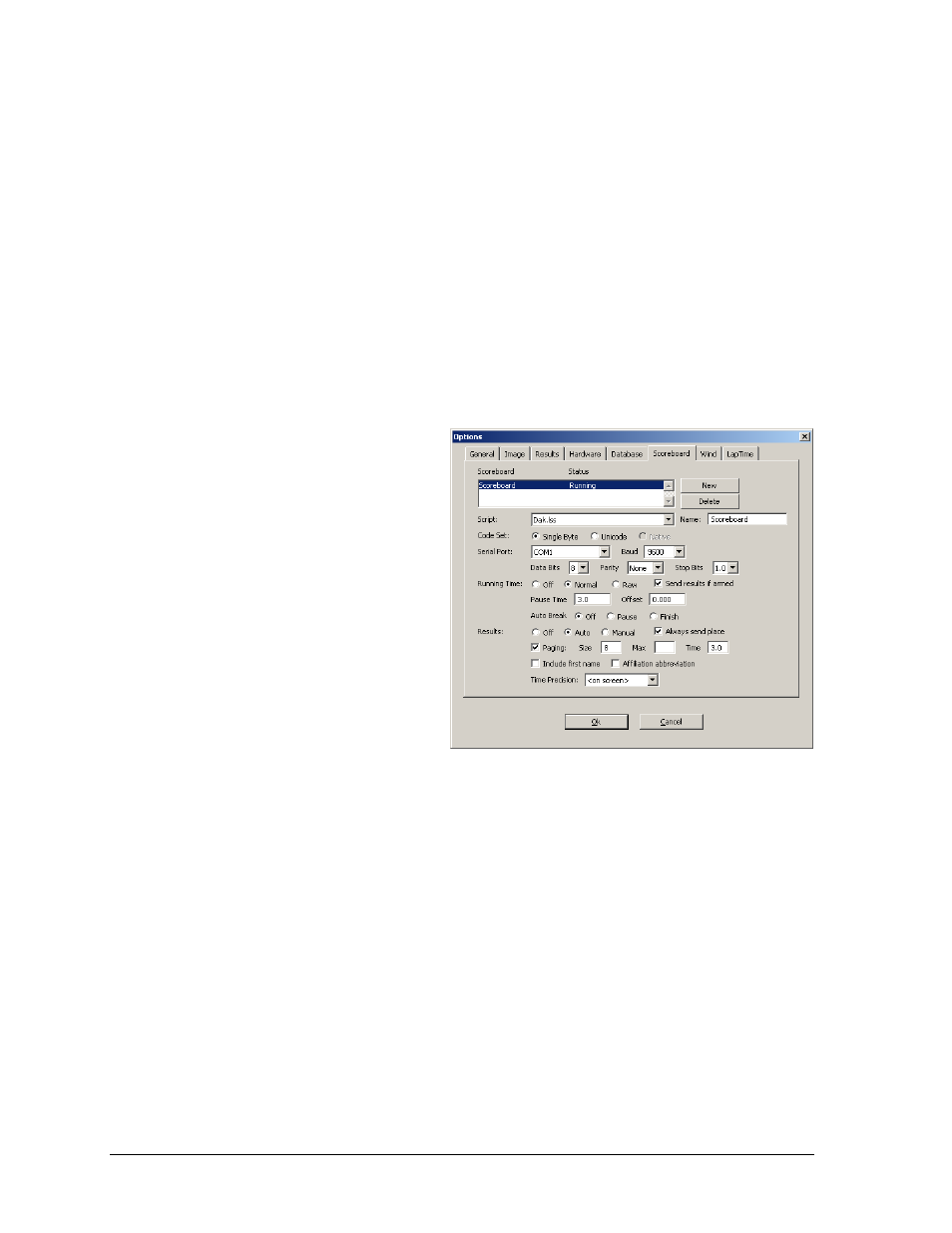
(refer also to Figure 7):
Script: “Dak.lss”
Name: “Scoreboard”
Code Set: Single Byte
Serial Port: Select an available
COM port.
Baud: 9600
Data Bits: 8
Parity: None
Stop Bits: 1.0
Running Time: Normal
Auto Break: Off
Results: Auto, Always send place enabled
Paging enabled; set the Size to the number of lanes that can be displayed on the
matrix display; Time “3.0”
Figure 7: Scoreboard Options for Venus/V-Play Via Serial