Light sensor replacement, Figure 36 – Daktronics Galaxy AF-3500 Series 46 mm User Manual
Page 40
36
Part Replacement
To replace a power supply:
1. Turn off power to the display.
2. Remove the module directly in
front of the appropriate power
supply.
3. Disconnect the Mate-N-Lok
®
connectors from the power
source as well as those going to
the modules. Label each
connector to ensure proper
reconnection.
4. Loosen the screw holding the
power supply bracket to the
cabinet upright and lift it off the
hooks.
5. Carefully pull the power supply out of the cabinet.
6. Move the new power supply into place and tighten the screw on the support bracket.
7. Reconnect all the Mate-N-Lok
®
plugs and the V Adjust cable so that each module
will receive power.
Light Sensor Replacement
Tools required:
3
/
16
" Nut driver, Phillips
screwdriver
Locate the light sensor assembly inside the
bottom left edge of the cabinet. Refer to Figure
22.
If the light sensor fails, replace the circuit board.
Remove the bottom left module on the display to
access the light sensor.
To replace a light sensor circuit board:
1. Remove the screws that hold the light
sensor to the cabinet. Refer to Figure 37.
2. Remove the #4-40 nuts securing the
circuit board to the plate.
3. Remove the standoffs and attachment
screws from the board.
4. Disconnect the four electrical wires on
the sensor by unscrewing each screw
that holds a wire in place. Note the order
of the wires to ensure proper
reconnection on the replacement. Do not
detach the light sensor plug on the controller.
5. Reattach the new circuit board, following these steps in reverse.
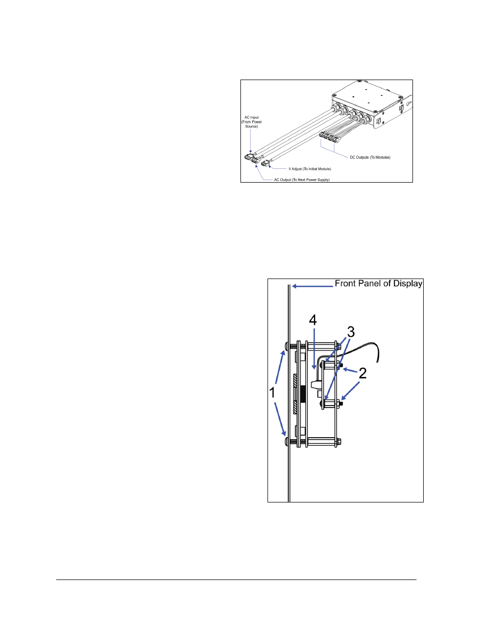
Figure 36: Power Supply
Figure 37: Light Sensor Assembly