Section 7: diagnostics and troubleshooting, 1 controller diagnostics, 2 mlc diagnostics – Daktronics Galaxy AF-3500 Series 46 mm User Manual
Page 29: Section 7, Diagnostics and troubleshooting, Controller diagnostics, Mlc diagnostics
Diagnostics and Troubleshooting
25
Section 7:
Diagnostics and Troubleshooting
Important Notes: Disconnect power when servicing the display. Only qualified service personnel
should service internal electronic components.
7.1 Controller Diagnostics
The controller is the “brains” of the
display. It receives communication from
the computer and sends information to the
modules. The controller is located in the
lower left area of displays. Refer to Figure
22. LEDs on the controller show whether
the power and communication signal are
working properly.
Mirror displays do not contain a controller.
Instead, they have a multi-line controller
(MLC), which helps relay information from
the primary controller.
To access the interior of the display, refer to
Section 6:. Remember to disconnect power
to the display before accessing the interior.
Remove the modules; inspect the wires for
safety, and then turn on power to view the
diagnostic LEDs.
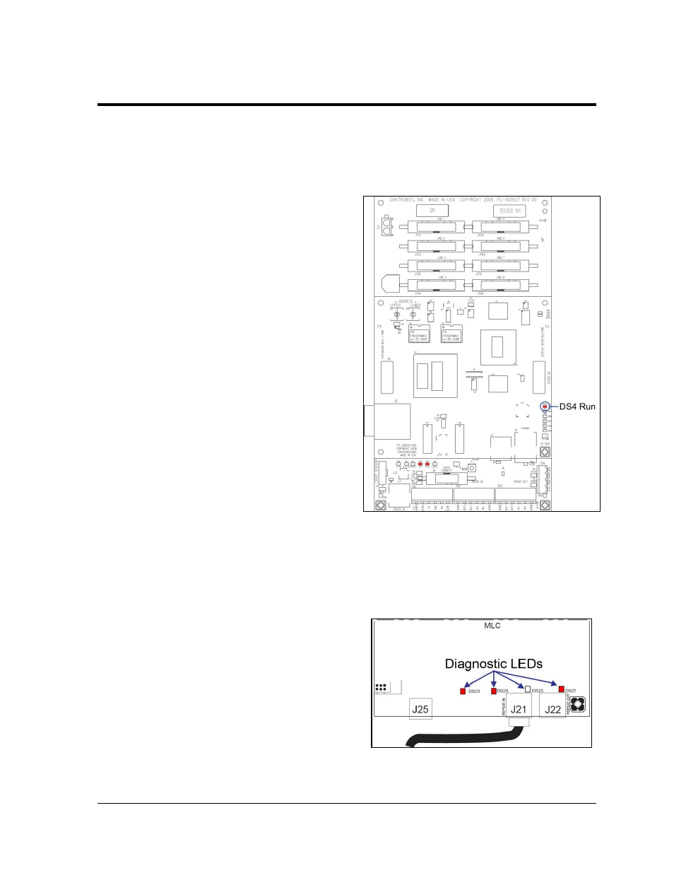
Refer to Figure 27 for an example of a
Galaxy
®
display controller. Essential
diagnostic LED:
The DS4 Run LED shows the controller’s operational status. This LED will flash once
per second to indicate that the controller is functioning properly.
7.2 MLC Diagnostics
The Multi-Line Controller (MLC) unit
contains four red diagnostic LEDs. When
properly connected to the primary display,
the LED labeled DS25 will be off and the
other LEDs will be on, as shown in Figure 28.
Figure 27: Controller Diagnostics
Figure 28: MLC Diagnostic LEDs