5 power connection, Power connection, On 3.5 – Daktronics Galaxy AF-3500 Series 46 mm User Manual
Page 15
Power Installation
11
Support structure cannot be used as an earth-ground electrode: Daktronics does not
recommend using the support structure as an earth-ground electrode; concrete, primer,
corrosion, and other factors make the support structure a poor ground.
Note: The support structure may be used as an earth-ground electrode only if designed
to do so. A qualified inspector must approve the support structure and grounding
methods.
One grounding electrode for each display face: The grounding electrode is typically one
grounding rod for each display face. Other grounding electrodes as described in any
local and national electrical codes may be used.
3.5 Power Connection
For most displays, power terminates externally at the J box. However, larger displays require
internal power termination at the power termination panel.
For Displays with an External Power Termination J box
To terminate hot, neutral, and ground wires at the J box:
1. Route the power cable through conduit to the rear of the display, and into the power
termination J box. The J box contains
3
/
4
" threaded conduit fittings.
2. The J box contains two or three wires, plus a ground coming from the interior of the
display. These wires pre-terminate at the power termination panel inside the display.
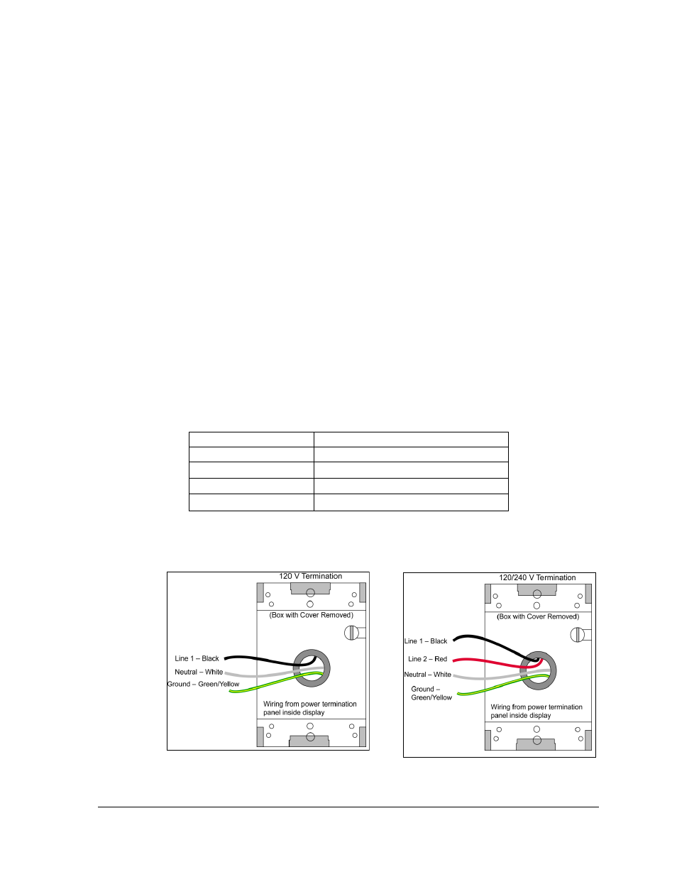
Refer to the following table for wire colors:
120 VAC
120/240 VAC
Line 1
– Black
Line 1
– Black
Line 2
– Red
Neutral
– White
Neutral
– White
Ground
– Green/Yellow
Ground
– Green/Yellow
3. Inside the external J box, use wire nuts to connect the power wires to the wires
coming from the display interior. Refer to Figure 11 for 120 V AC and Figure 12 for
120 / 240 V AC.
Figure 11: 120 V J box Termination
Figure 12: 120 / 240 V J box Termination