Mlc replacement, Power supply replacement – Daktronics Galaxy AF-3500 Series 46 mm User Manual
Page 39
Part Replacement
35
MLC Replacement
Tools required:
1
/
8
" Hex wrench,
5
/
16
" Nut driver, Flathead screwdriver
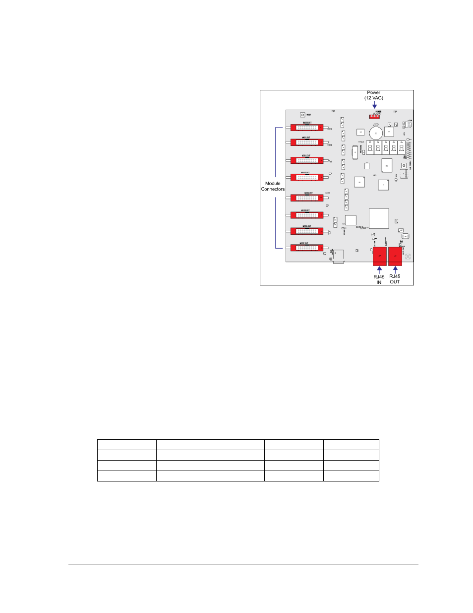
In mirror displays, the multi-line controller
(MLC) receives signal from the primary
controller and distributes it to the modules.
Ribbon cables run from the module connectors
on the MLC to the first modules in each row
via ribbon cables. The power supply nearest
the MLC will provide its power via a
transformer, which receives power from the
power termination panel.
1. Turn off power to the display.
2. Remove the module directly in front of
the MLC. Refer to Figure 22 for the
approximate location.
3. Disconnect the input cables.
4. When removing all ribbon cables label
the module numbers to ensure proper
replacement.
5. Remove the six nuts holding the board
in place using a
5
/
16
" nut driver.
6. To install the new MLC, move the unit
into place and replace the six nuts
holding it to the display back.
7. Reconnect input and ribbon cables.
8. Turn on power and observe the start-up sequence. Note that the LEDs to the right of
the fiber jacks are on; DS23 to the left of the fiber cable should be off. Refer to Figure
28 and Figure 35 for more information.
Power Supply Replacement
Tool required: Phillips screwdriver
Galaxy
®
46 mm displays use two different power supplies, depending on the type of module
used. Displays with red modules use 135-watt power supplies. Displays with amber or RGB
modules use 150-watt power supplies.
Module Type
Modules per Power Supply Voltage
Outputs
Red
Eight
6.5
2 pin DC
Amber
Six
11.6
4 pin DC
RGB
Three
9.2
4 pin DC
A Mate-N-Lok
®
cable connects each module to a wire harness on the power supply. Refer to
The V adjust cable connects to a module and is used to calibrate the power supply to the
appropriate module voltage. If this cable is not connected, the section of modules will appear
dimmer than the rest of the display.
Figure 35: Multi-Line Controller