Section 4: signal installation, 1 overview of signal connection, 2 primary/mirror display interconnections – Daktronics Galaxy AF-3500 Series 46 mm User Manual
Page 17: Section 4, Signal installation, Overview of signal connection, Primary/mirror display interconnections
Signal Installation
13
Section 4:
Signal Installation
For specific details on installing communications, consult the quick guide and manual included with
the communication equipment. Refer to the table below for the standard communication types and
their corresponding manual number. These are the standard communication types. Each site is
unique and may include additional equipment. If problems arise, contact the display’s service
company or Daktronics Customer Service.
Communication Type
Communication Manual
Communication Quick Guide
Ethernet
Fiber Ethernet
Wireless Ethernet Bridge
Wi-Fi
USB to Ethernet Adapter
N/A
4.1 Overview of Signal Connection
Refer to the communication manuals for methods of signal termination.
Route signal cable to the signal termination enclosure. Ground the enclosure to an
isolated earth ground connector (when required).
Route signal cable through conduit into the enclosure. Use
3
/
4
" conduit for the knockouts
on the enclosure.
Route signal quick-connect cables through conduit, from the enclosure to the display.
Optionally, you can route signal through the display pole; however, do not route signal
through the display pole if routing power through the display pole.
Note: Daktronics strongly recommends that the quick-connect cables be secured to
protect them from weather or vandalism.
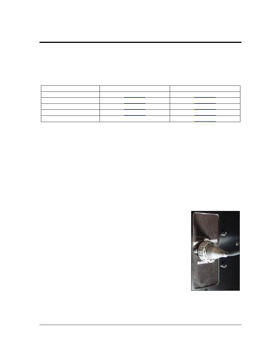
4.2 Primary/Mirror Display Interconnections
If this display is a two-sided primary/mirror display, a 20'
quick-connect cable will be provided to connect the signal
between the two faces. This cable cannot be lengthened. Refer
to Figure 15.
Secure the excess cable to the support structure to prevent
weather damage or vandalism.
Figure 15: Primary/Mirror
Quick-connect Cable