Controller replacement, Controller address setting – Daktronics Galaxy AF-3500 Series 46 mm User Manual
Page 38
34
Part Replacement
Controller Replacement
Tools required:
1
/
8
" Hex wrench,
5
/
16
" Nut driver, Flathead screwdriver
To replace a controller in the display:
1. Turn off power to the display.
2. Remove the module directly in front
of the controller in the lower left
area of the display. Refer to Figure
22 for the location.
3. Loosen the screws and remove the
cover in front of the controller.
4. Disconnect the power input.
5. Remove all power and signal
connections from the board. Label
the cables as to ensure proper
replacement.
6. Remove the six nuts holding the
board in place using a
5
/
16
" nut
driver.
7. Take note of the rotary address on
the controller to ensure the address
on the replacement board is the
same. Refer to the Controller
Address Setting section for
additional information. Refer to
Figure 33 and Figure 34.
8. To install the new controller, replace the six nuts holding it to the display back.
Reconnect power and signal cables. Turn on power, observe the start-up sequence,
and then note that the pixel in the lower-right corner shows power.
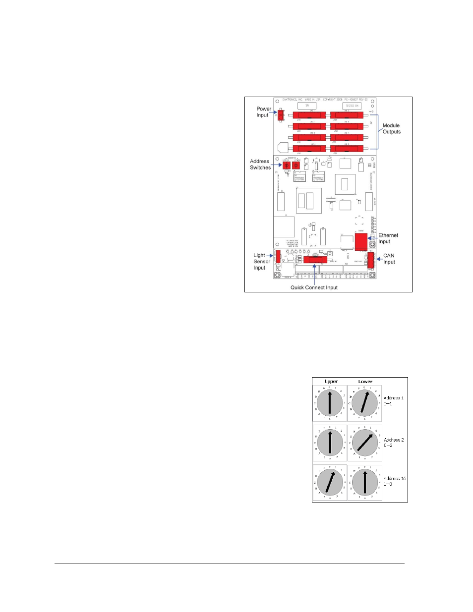
Controller Address Setting
The rotary switches set the hardware address, which the
software uses to identify each particular display. Each controller
in a network needs a unique address.
To set the rotary address switches, rotate them until the arrow
points to the desired number. To activate test mode or to change
an address, turn off power to the display and then turn it back
on.
Notes:
Setting both rotary switches to address 0 will activate
Test Mode. Turn the display's power off and back on to
activate testing.
After testing, reset the rotary switches to an address
other than 0/0 and repower the controller (the software
will not recognize an address of 0).
Figure 33: Galaxy Controller
Figure 34: Rotary Address
Switches