For displays with internal power termination, 6 power routing in the display, Power routing in the display – Daktronics Galaxy AF-3500 Series 46 mm User Manual
Page 16
12
Power Installation
For Displays with Internal Power Termination
To terminate single-phase power to the internal power termination panel:
1. Open the display as explained in Section 6:
and locate the power termination panel.
2. Route the cable through conduit to the back of
the display. Use the
3
/
4
" knockout for access,
careful not to damage internal components.
3. Connect the neutral wire to the neutral lug and
the live wires to the Line 1 and Line 2 lugs.
4. The ground wire connects to the grounding
bus bar. Refer to Figure 13.
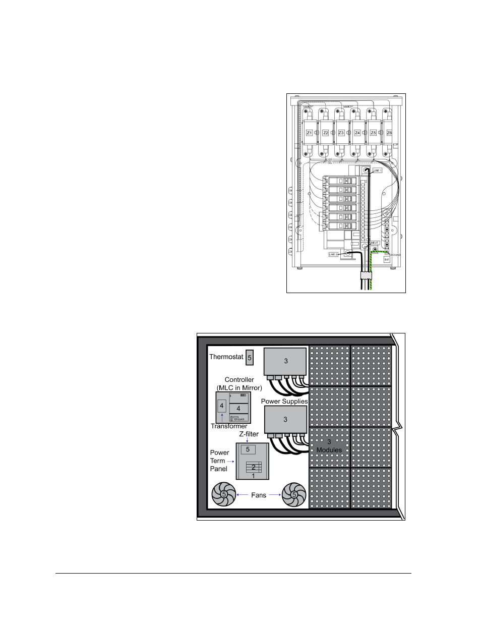
3.6 Power Routing in the Display
The following list is a summary of power routing. The
list refers to the numbers in Figure 14.
1. Power terminates internally to the power
termination panel (either directly or via the
rear-mounted J box).
2. Power routes through the circuit breakers and
the Z-filter in the power termination panel.
3. Power routes through filters to the power
supplies, which provide power to the modules.
4. Power travels
through the
transformer, which
steps down power to
the appropriate
voltage for the
controller (or MLC in
a mirror display).
5. Power routes
through a filter to the
thermostat and the
fans. The thermostat
activates the fans.
Note: Power supplies
are set to the proper
voltage via the V
adjust harness that is
connected to the
nearest module.
Figure 13: Single-phase 6-breaker
Domestic Panel
Figure 14: Power Flow Summary