3 channel configuring, 1 analog voltage input configuring, Channel configuring – Contemporary Control Systems BASremote User Manual (firmware 3.1.x) User Manual
Page 38: Analog voltage input configuring
TD040300-0MF
38
6.3 Channel Configuring
To configure a channel, access the Web Server Page, click on the
icon for the channel
of interest and make adjustments in the new screen that appears. Your selected channel is
confirmed by the large number on the left side of the new screen. As Figure 24 shows,
clicking on the Save button is confirmed by the button briefly changing from light blue to dark
blue. If you attempt to set an illegal value, the button will not change colour.
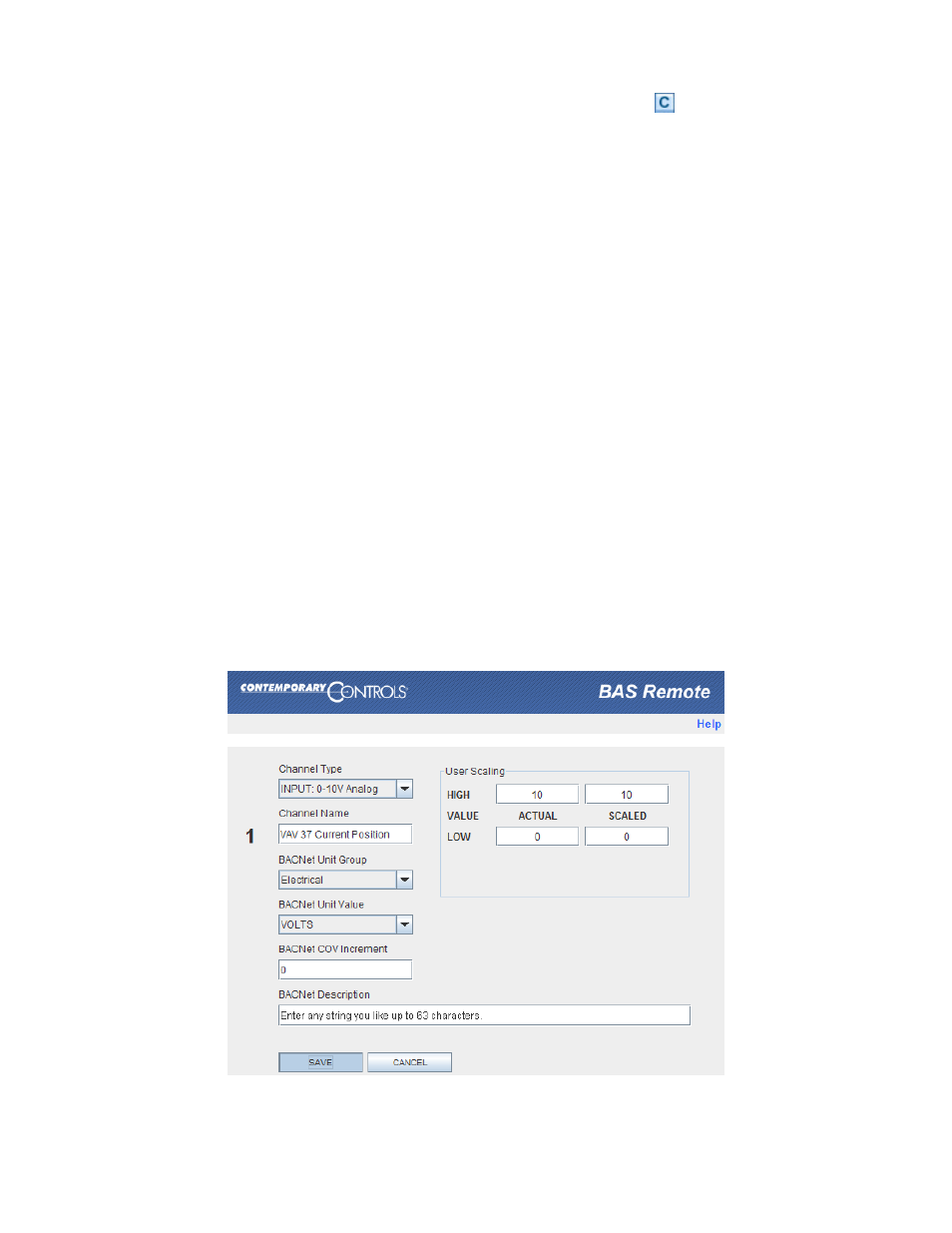
6.3.1 Analog Voltage Input Configuring
You can define any channel 1
–6 as “INPUT: 0–10V Analog” or “INPUT: 0–5V Analog” (As an
example, Figure 24 uses Channel 1 and 0
–10V). Such a channel can accept an input voltage in
the range of 0
–10 volts or 0–5 volts. The channel BACnet type will be Analog Input. On this
screen, you can adjust these parameters:
BACnet Unit Group
The Electrical default can be set to any option in the list.
Channel Name
You can rename the channel using no more than 63 characters.
This will be the object name for this channel (followed by the
channel number). For example,
“Analog Input-1”.
BACnet Unit Group
The Electrical default can be set to any option in the list.
BACnet Unit Value
The VOLTS default can be set to any option in the list. The available
options depend on the BACnet Unit Group you specify.
BACnet COV Increment Once the channel value changes by this amount (up or down), a
COV message is sent to subscribers.
BACnet Description
You can enter any string using no more than 63 characters.
ACTUAL HIGH
This specifies the highest value within the range.
ACTUAL LOW
This specifies the lowest value within the range.
SCALED HIGH
You can set a physical value corresponding to the high value.
SCALED LOW
You can set a physical value corresponding to the low value.
Figure 24
— Analog Input Configuration