5 field connections, 1 sample bas remote wiring diagram, Field connections – Contemporary Control Systems BASremote User Manual (firmware 3.1.x) User Manual
Page 21: Sample bas remote wiring diagram
TD040300-0MF
21
5 Field Connections
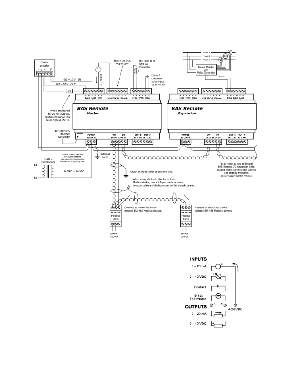
5.1 Sample BAS Remote Wiring Diagram
Figure 6
— Sample BAS Remote Wiring Diagram
Wire Channels 1
–6 so the most positive wire goes to
the “A” terminal and the most negative wire to the “B”
terminal.
The wiring options for Channels 1
–6 are shown in
Figure 7. For each case in which polarity matters,
proper polarity is indicated.
Considerations in making field connections for various
types of input and output devices are discussed in the
following pages.
Figure 7
— I/O Options (Channels 1–6)
This manual is related to the following products: