2 thermistors, 3 contact closure, Thermistors – Contemporary Control Systems BASremote User Manual (firmware 3.1.x) User Manual
Page 22: Contact closure
TD040300-0MF
22
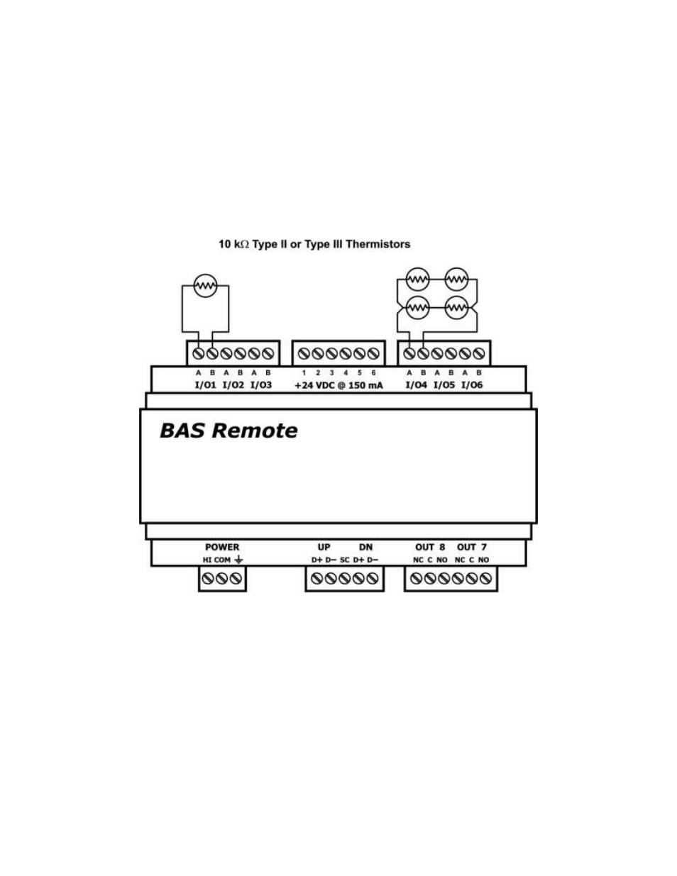
5.2 Thermistors
The BAS Remote has built-
in calibration curves for 10 kΩ Type II or Type III thermistors.
These devices have a non-linear with a negative coefficient of resistance to temperature
and provide a nominal resistance
of 10 kΩ at 25°C. Using the web server, configure an
input for either Type II or Type III thermistor. As shown in Figure 8, connect the two-
wire thermistor to points A and B. Polarity is not an issue. If averaging of temperature
is desired, connect multiple thermistors in a series-parallel combination so that the nominal
resistance remains at 10 kΩ as shown. Make sure that all devices are of the same type.
The effective range of temperature measurement is from +40° to +110°F (+4.4° to
+44°C). An open input results in a fault condition that produces a red LED indication for
that channel.
Figure 8
— Thermistor Connections
5.3 Contact Closure
The BAS Remote can sense the make or break of a contact from a relay or push-button.
The contacts being sensed must be absent of any applied source of energy, and be
rated for low-voltage, low-current switching. The BAS Remote will provide the electrical
energy to be sensed. Using the web server, configure an input for contact closure. As
shown in Figure 9, simply connect the contacts between points A and B. For common
mechanical contacts, polarity is not an issue. The open-circuit voltage is 24 VDC and the
short-circuit current is 2 mA.