2 ‘j6 | com1’ connector, 3 ‘j8 | input sample’ connector, 4 ‘j9 | output sample’ connector – Comtech EF Data HPOD User Manual
Page 34
HPOD C-, X-, Ku-Band High-Power Outdoor Amplifier
MN/HPOD.IOM
External Connectors and Pinouts
Revision 8
2–8
2.5.2 ‘J6 | COM1’ Connector
The ‘J6 | COM1’ Discrete Control connector is the primary input for controlling and monitoring
the SSPA. It is a 19-pin circular connector, type MS3112E14-19S. The pinout specification is
shown in Table 2-6.
Mating connector: ITT: KPT06J14-19P or MS3116J14-19P.
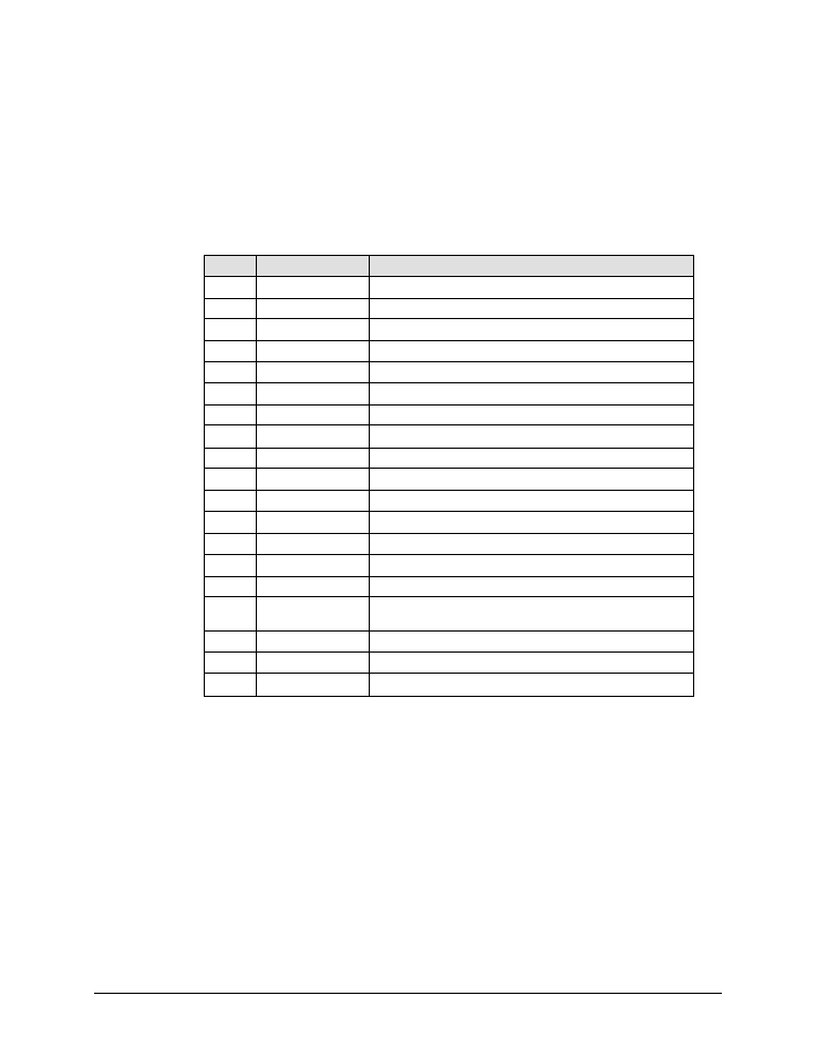
Table 2-6. ‘J6 | COM1’ Connector Pinout
Pin
Name
Description
A
RS485_+RX
B
RS485_-RX
C
RS485_+TX
D
RS485_-TX
E
RS232_RD
F
Ethernet TX+
G
RS232_TD
H
Ethernet TX-
J
Aux_Out
Not for customer use
K
SumFLT_COM
L
SumFLT_NO
Open when faulted, else tied to Pin K.
M
SumFLT_NC
When faulted, tied to Pin K, else open.
N
GND
P
ONLINE_Status
Not for customer use
R
+24V
Not for customer use
S
Mute Control
When AUX=1, system is muted until this pin is pulled to ground.
At that time, the unit unmutes. See the AUX remote command.
T
Minor_FLT_COM Reserved for future use
U
Ethernet RX-
V
Ethernet RX+
2.5.3 ‘J8 | INPUT SAMPLE’ Connector
The ‘J8 | INPUT SAMPLE’ port connector is a Type ‘N’ female. It provides a nominal –20 dB
sample of the input signal. A calibration label is provided near the connector that shows the
actual coupling values vs. frequency.
2.5.4 ‘J9 | OUTPUT SAMPLE’ Connector
The ‘J9 | OUTPUT SAMPLE’ port connector is a Type ‘N’ female. It provides a nominal -40 dB
sample of the output signal. A calibration label is provided near the connector that shows the
actual coupling values vs. frequency.