B.2.8 crs-351 – overhead module connector (db-25m) – Comtech EF Data CRS-311 User Manual
Page 179
CRS-311 1:1 Redundancy Switch
Revision 7
Appendix B
MN/CRS311.IOM
B–11
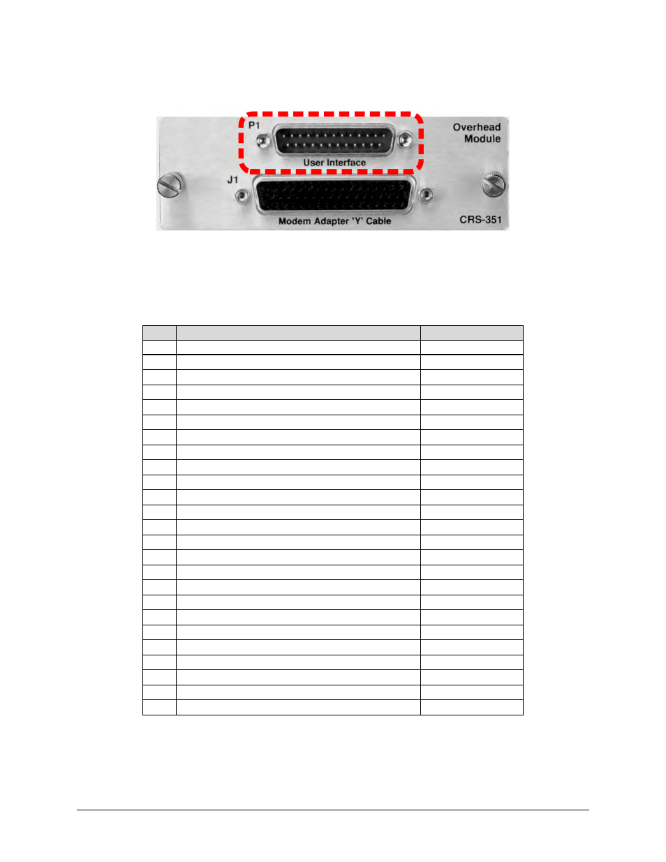
B.2.8 CRS-351 – Overhead Module Connector (DB-25M)
Table B‐11 indicates pinout for the DB‐25M Overhead “User Interface” connector: “P1” on the
CRS‐351 Overhead Module. This connector allows for connection of EIA‐422, EIA‐485 and EIA‐232
data interfaces for use with Overhead Framing. It also supports signaling for tactical applications.
Table B-11. “P1” Overhead User Data Connector
Pin # Signal Function
Name
1
EIA-422 Transmit Data “A”, Input
Tx Data A
14 EIA-422 Transmit Data “B”, Input
Tx Data B
2
EIA-422 Transmit Clock “A”, Output
Tx Clk A
15 EIA-422 Transmit Clock “B”, Output
Tx Clk B
3
EIA-422 Transmit Byte Sync “A”, Output
Tx Sync A
16 EIA-422 Transmit Byte Sync “B”, Output
Tx Sync B
4
EIA-422 Receive Data “A”, Output
Rx Data A
17 EIA-422 Receive Data “B”, Output
Rx Data B
5
EIA-422 Receive Clock “A”, Output
Rx Clk A
18 EIA-422 Receive Clock “B”, Output
Rx Clk B
6
EIA-422 Receive Byte Sync “A”, Output
Rx Sync A
19 EIA-422 Receive Byte Sync “B”, Output
Rx Sync B
7 Shield
Ground
20 EIA-485 Transmit Data “-“
485 Tx Data -
8
EIA-485 Transmit Data “+”
485 Tx Data +
21 EIA-422 Transmit Handover Sync “A”, Input
THS A
9
EIA-485 Receive Data “-“
485 Rx Data -
22 EIA-485 Receive Data “+”
485 Rx Data +
10
EIA-422 Transmit Handover Sync “B”, Input
THS B
23 EIA-232 Clear to Send
232 CTS
11
EIA-232 Receive Data
232 Rx Data
24 EIA-232 Request to Send
232 RTS
12
EIA-232 Transmit Data
232 Tx Data
25 EIA-422 Transmit Handover Control “A”, Input
THC A
13
EIA-422 Transmit Handover Control “B”, Input
THC B
*For EIA‐485 2‐Wire Operation:
• Only two wires are required.
• Tie pins 8 and 22 together (both +).
• Tie pins 9 and 20 together (both ‐).