B.1.2 crs-230 “485 pass-through” connector (db-9f), B.1.3 crs-230 “remote control” connector (db-9m) – Comtech EF Data CRS-311 User Manual
Page 170
CRS-311 1:1 Redundancy Switch
Revision 7
Appendix B
MN/CRS311.IOM
B–2
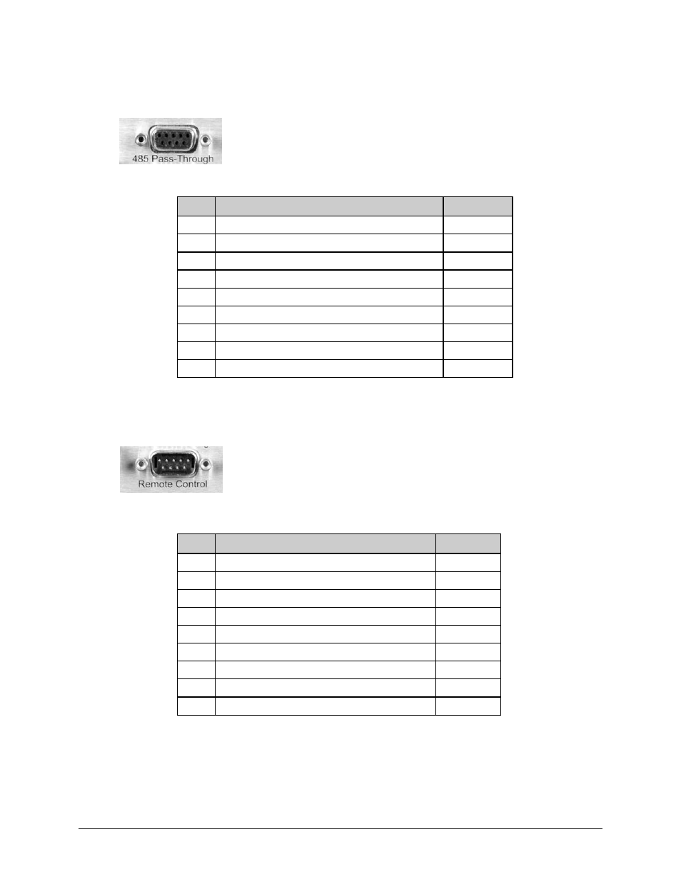
B.1.2 CRS-230 “485 Pass-Through” Connector (DB-9F)
Table B‐1 indicates the pinout for the CRS‐230 “485 Pass‐Through”
connector. This connector is used only with the CDM‐Qx/QxL modems.
Table B-1. “485 Pass-Through” User Data Connector
Pin # Description
Direction
1 Ground
–
6
RS-485 Receive Data B (see Note) In
2 RS-232 Transmit Data
Out
7
RS-485 Receive Data A (see Note) In
3 RS-232 Receive Data
In
8
RS-485 Transmit Data B
Out
4 Reserved - do not connect to this pin
–
9
RS-485 Transmit Data A
Out
5 Ground
–
Note: Use for 2‐wire RS‐485 operation.
B.1.3 CRS-230 “Remote Control” Connector (DB-9M)
Table B‐2 indicates the pinout for the CRS‐230 DB‐9M “Remote Control”
connector. This connector provides access to the remote control ports of
the CRS‐311 for both EIA‐232 and EIA‐485.
Table B-2. “Remote Control” User Data Connector
Pin # Description
Direction
1 Ground
–
6
EIA-485 Receive Data B (see Note) In
2 EIA-232 Transmit Data
Out
7
EIA-485 Receive Data A (see Note) In
3 EIA-232 Receive Data
In
8
EIA-485 Transmit Data B
Out
4 Reserved - do not connect to this pin
–
9
EIA-485 Transmit Data A
Out
5 Ground
–
Note: Use for 2‐wire EIA‐485 operation.