3 sercos interface (x7), option, 1 light emitting diodes (leds), 2 connection diagram – BECKHOFF AX2500 User Manual
Page 70: Sercos interface, Sercos interface (x7), option
8.18.3
SERCOS interface (X7), option
This section describes the SERCOS interface of the AX2500. Information on the range of
functions and the software protocol can be found in the manual “IDN Reference Guide
SERCOS”.
For the fiber optic cable connection, only use SERCOS components to the SERCOS
Standard IEC 61491.
8.18.3.1
Light emitting diodes (LEDs)
RT
Indicates whether SERCOS telegrams are being correctly received. In the final
Communication Phase 4 this LED should flicker, since cyclical telegrams are
being received.
TT
Indicates that SERCOS telegrams are being transmitted. In the final Communi-
cation Phase 4 this LED should flicker, since cyclical telegrams are being trans-
mitted. Check the stations addresses for the controls and the servo amplifier if:
- the LED never lights up in SERCOS Phase 1 or
- the axis cannot be operated, although the RT LED is lighting up cyclically.
Err
Indicates that SERCOS communication is faulty or suffering from interference.
If this LED is very bright, then communication is suffering strong interference, or
is non-existent. Check the SERCOS transmission speed for the controls and the
servo amplifier (BAUDRATE) and the fibre-optic connection.
If this LED flickers, this indicates a low level of interference for SERCOS com-
munication, or the optical transmitting power is not correctly adjusted to suit the
length of cable. Check the transmitting power of the (physically) previous SER-
COS station. The transmitting power of the servo amplifier can be adjusted in
the setup software DRIVE.EXE on the SERCOS screen page, by altering the
parameter for the cable length.
8.18.3.2
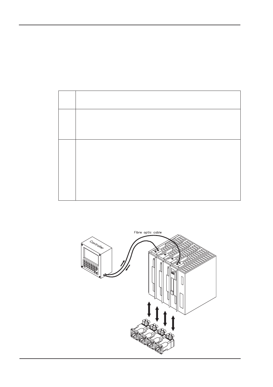
Connection diagram
Layout of the SERCOS bus system in ring topology, with optical fibre cables (schematic).
70
AX2500 Product Manual
Electrical Installation
06/2007
BECKHOFF