BECKHOFF AX2500 User Manual
Digital servo amplifier ax2500
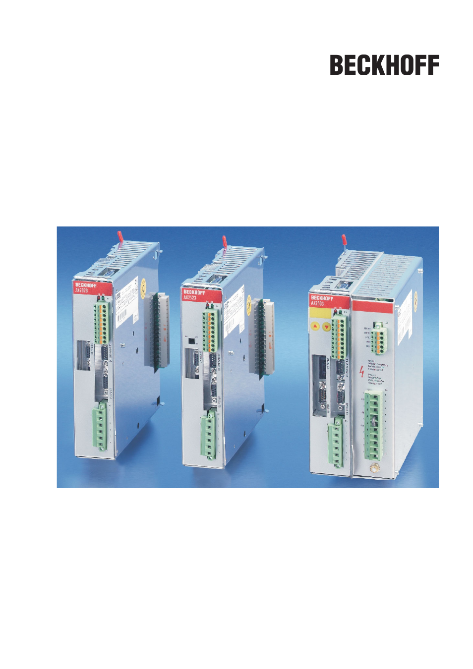
Table of contents
Document Outline
- Cover page
- Contents
- 1 General
- 2 Safety
- 3 Standards
- 4 Handling
- 5 Package
- 6 Technical description
- 7 Mechanical Installation
- 8 Electrical Installation
- 8.1 Important notes
- 8.2 Guide to electrical installation
- 8.3 Wiring
- 8.4 Components of a servo system
- 8.5 Block diagram
- 8.6 Connector assignments
- 8.7 Connection diagram AX250x and AX251x (overview)
- 8.8 Connection diagram AX252x (overview)
- 8.9 Power supply, master only
- 8.10 DC Bus link (X0)
- 8.11 Motor connection with brake (X6)
- 8.12 External regen resistor (X0), master only
- 8.13 Feedback
- 8.14 Electronic Gearing, Master-slave operation
- 8.15 Encoder emulations
- 8.16 Digital and analog inputs and outputs
- 8.17 RS232 interface, PC connection (X8), master only
- 8.18 Fieldbus connection
- 9 Setup
- 9.1 Important notes
- 9.2 Setup software
- 9.3 Quickstart, drive test
- 9.4 Multi-axis systems
- 9.5 Key pad controls and status displays
- 9.6 Error messages
- 9.7 Warning messages
- 9.8 Trouble Shooting
- 10 Appendix
- Index
- !
- A
- B
- C
- D
- E
- F
- G
- H
- I
- K
- L
- M
- N
- O
- P
- Q
- R
- S
- T
- U
- V
- W