15 encoder emulations, 1 incremental encoder output - a quad b (x4), Encoder emulations – BECKHOFF AX2500 User Manual
Page 61: Rod, interface, Incremental encoder output - a quad b (x4)
8.15
Encoder emulations
8.15.1
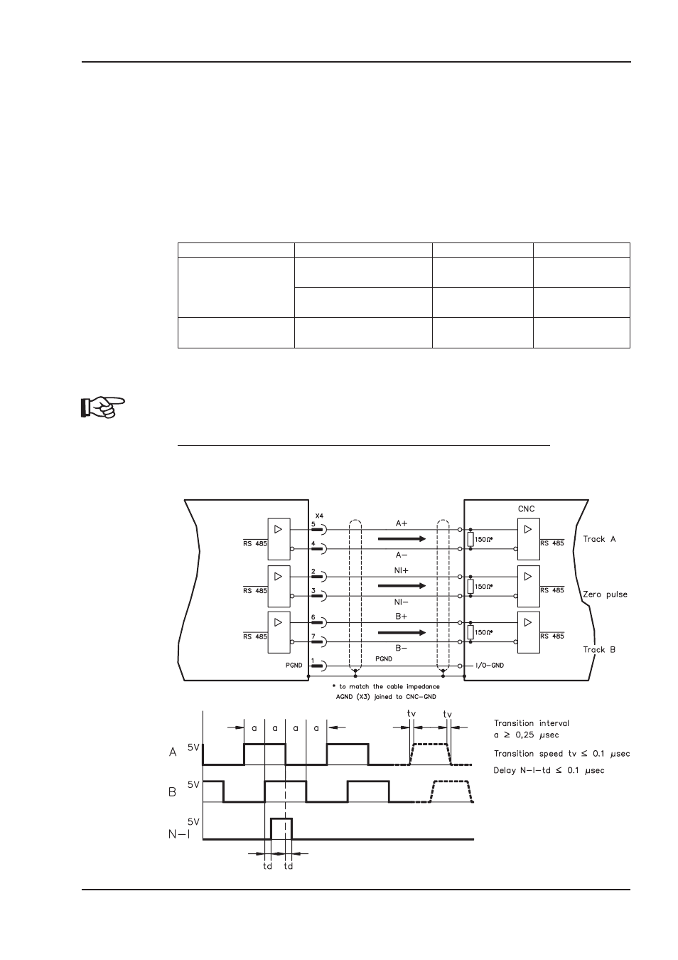
Incremental encoder output - A quad B (X4)
The incremental-encoder interface is part of the package supplied. Select the encoder
function ROD (screen page “Encoder”, funktion ENCMODE). In the servo amplifier, the
position of the motor shaft is calculated from the cyclic-absolute signals of the resolver or
encoder.
Incremental-encoder compatible pulses are generated from this information. Pulses are
output as two signals, A and B, with 90° phase difference and a zero pulse. The resolu-
tion (lines before quadrature) can be changed with the RESOLUTION parameter:
Encoder function
Feedback system
Resolution
Zero position
ROD (1)
Resolver
256...4096
one per revolution
(only if A=B=1)
Encoder
256...524288
(2
8
... 2
19
)
one per revolution
(only if A=B=1)
ROD interpolation (3) Encoder
2
2
...2
7
TTL
lines per sine line
analog pass
through X2 to X4
You can also adjust and store the position of the zero pulse within one mechanical turn
(parameter NI-OFFSET). The ground reference for the interface is PGND.
PGND must always be connected to the control ground. The max. admissible cable
length is 10 m.
Connections and signal description for the incremental-encoder interface :
The count direction is UP when the motor shaft is rotating clockwise (looking at the end of
the motor shaft).
AX2500 Product Manual
61
BECKHOFF
06/2007
Electrical Installation
AX2500