6 connectors - rear panel, 2 external input/ output signal connector – AMETEK CSW Series User Manual
Page 35
User Manual
California Instruments
CSW Series
35
3.6 Connectors - Rear Panel
A number of connectors are located on the rear panel of the power source. The connectors are
identified by J numbers. The terminal strips are identified by TB numbers.
3.6.1 System Interface, Clock and Lock Connectors, J33 and J34
J33 and J34 are the Clock and Lock connectors. These connectors are only available with the
LK option. The LK option is used to synchronize and control the phase shift between the Phase
A output of the Master power source and the Phase A output of additional auxiliary power
sources. The frequency of the auxiliary power sources is determined by the frequency of the
master source. Refer to Figure 3-6 for the Clock and Lock connections to three power sources.
The System Interface connectors, J28A and J28B, are used to connect the Auxiliary power
sources to the Master power source in multiple source systems. The power that is to be the
Master source will have the System Interface cable plugged into its connector labeled “To
Auxiliary”, J28B. The other end of the System Interface cable will plug into J28A, labeled “To
Master”, of the first Auxiliary power source. Additional Auxiliary power sources will be chained
together with additional System Interface cables. Refer to Figure 3-4 for the System
Interconnect. Not available with FC option.
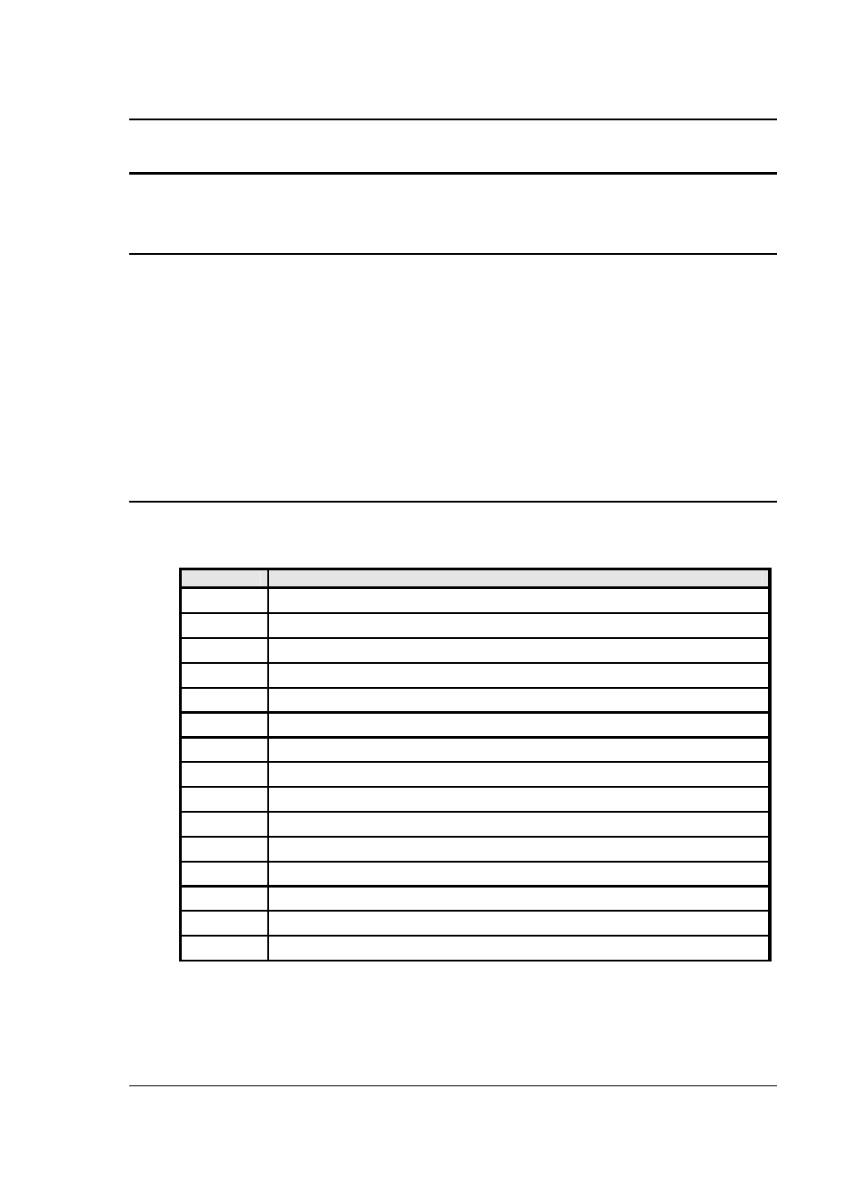
3.6.2 External Input/ Output Signal Connector
The External Input/ Output Connector is J32 on the rear panel. Table 3-2 shows the function for
each pin of this connector.
J32
Description
1
External Signal A: The input for an external signal or RPV for Phase A referenced to pin 10
2
External Signal C: The input for an external signal or RPV for Phase C referenced to pin 10
3
MOD A: The input for an amplitude modulation for Phase A referenced to pin 12
4
MOD C: The input for an amplitude modulation for Phase C referenced to pin 12
5
SYNC-HI: The Hi input for the TTL External Sync input.
6
ISOCOM: The common for the RTIN and /INHIBIT functions
7
/INHIBIT: A logic Lo or contact input to inhibit the outputs referenced to pin 6
8
DFI: Pins 8 and 15 are the two pins for the isolated DFI function
9
External Signal B: The input for an external signal or RPV for Phase B referenced to pin 10
10
External Signal Common: The common for all external signal or RPV inputs
11
MOD B: The input for an amplitude modulation for Phase B referenced to pin 12
12
MOD-COM: The common for all amplitude modulation inputs
13
SYNC-LO: The Lo input for the TTL External Sync input
14
RTIN: An input to trigger a function, referenced to pin 6
15
DFI: Pins 8 and 15 are the two pins for the isolated DFI function
Table 3-2: System Interface Connector (J32)