AMETEK CSW Series User Manual
Page 120
User Manual
California Instruments
120
CSW Series
5.4 Non-Routine Calibration
All internal adjustments are set at the factory at the time or original shipment. As such, non-
routine calibration is generally not required unless one or more amplifier assemblies have been
replaced in the field. In this case, perform the following sections in the order shown.
The non-routine calibration involves removing the top cover from the power source. Remove the
line power from the power source before removing the top cover. All of the adjustments are on
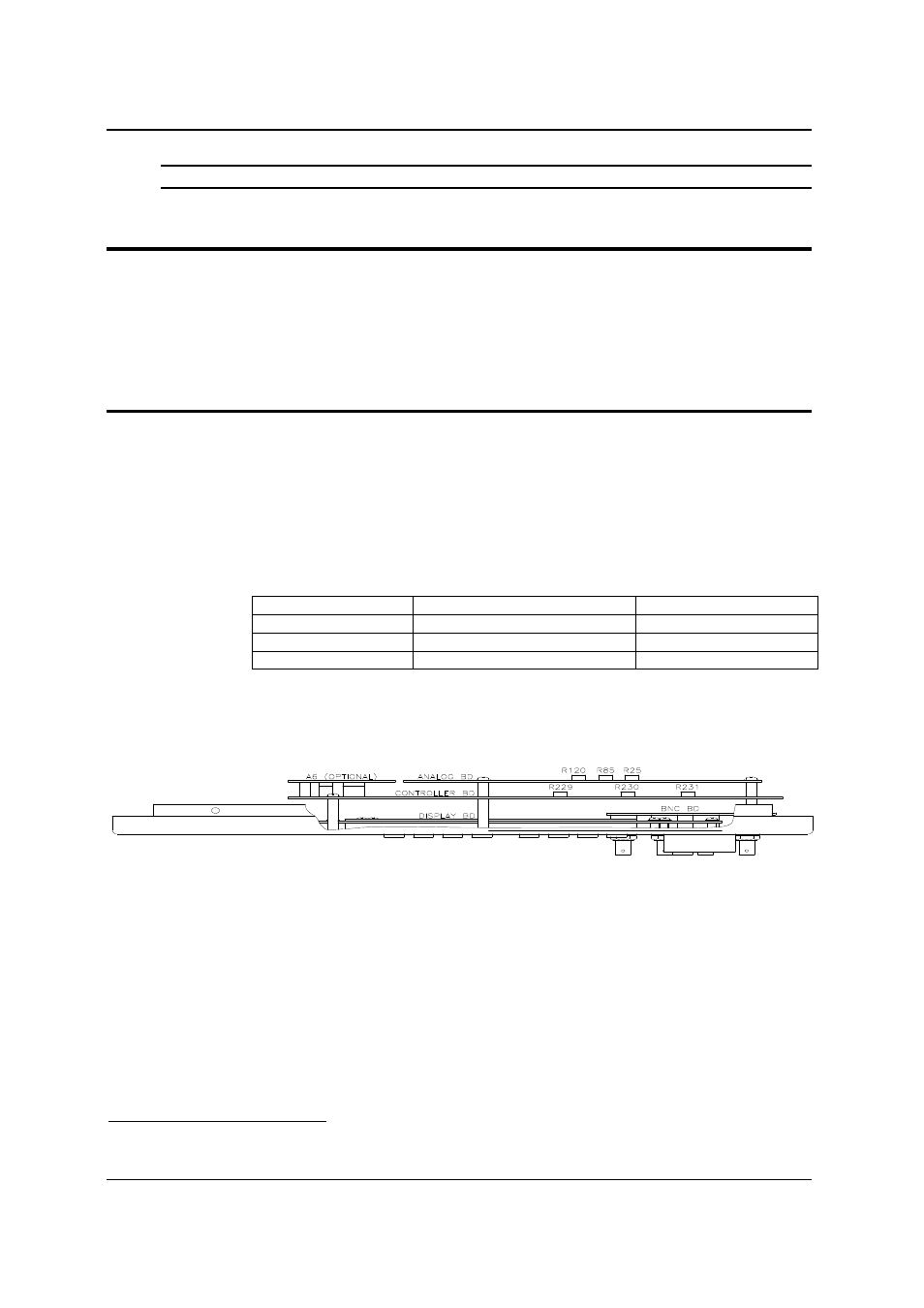
the Front Panel Assembly as shown in Figure 6-2.
5.4.1 AC Function AC Zero Adjustment (ALC can be either ON or OFF)
1. With the external DVM monitor the voltage at the power source output indicated in Table
6-3.
2. Press the PHASE key to indicate the corresponding phase to be adjusted.
3. Program the High Voltage Range, the AC function, 0.0 volts and 400 Hz.
4. Press the OUTPUT key to turn on the CSW. Perform the adjustment indicated in Table
3-1 for the indicated output phase. Make the adjustment for the lowest AC output signal.
Refer to Figure 6-2 for the location of the adjustments. The external DVM should be on
the 10 or 20 VAC range
1
.
Output Phase
Controller Brd Adjustment
Adjustment Location
A
R229
Left
B
R230
Middle
C
R231
Right
Table 6-3 AC Zero Adjustment
Figure 5-2: Front Panel Assembly Adjustment Location (Top View)
1
Use the 10 or 20 VAC or VDC range to prevent an offset error in the External DVM caused by output noise.