AMETEK CSW Series User Manual
Page 115
User Manual
California Instruments
CSW Series
115
5.3 Routine Calibration
Connect the test equipment to the power source as shown in Error! Reference source not
found.1. The AC output calibration does require an AC DVM operating with the highest
accuracy. Either a Fluke 8506A or a HP 34401A may be used. If a HP 34401A is used it must
be put into the slow filter mode.
5.3.1 Voltage Measurement Calibration, AC and DC
1.
Program the power source and the External DMM to the AC function and 100 Hz.
2.
Remove all of the output loads from the power source.
3.
Connect DMM to phase A output.
4.
Program the ALC OFF, the output to the AC mode, 312 volt range, 230 volts.
5.
Go to the Measurement Calibration Screen. Type 5000 as the password. Press the PHASE
key to select Phase A. Enter actual output (from external DMM) as the value for Phase A.
NOTE: If using the CSW GUI to perform Measurement Calibration the password is
“CAL_LOCK”.
6.
Repeat steps 3 through 4 for the Phase B and C outputs.
7.
Program the source and External DMM to the DC function. Repeat steps 2 through 6.
5.3.2 Current Measurement Calibration, AC and DC
1.
Program the power source and External DMM to the AC function.
2.
Connect the load and the Current Shunt to the Phase A output as shown in Figure 6-1.
Connect the Current Shunt to the Neutral output so it does not have to be moved when
switching the load to the other phases. Connect the External DMM to the sense terminals of
the Current Shunt.
3.
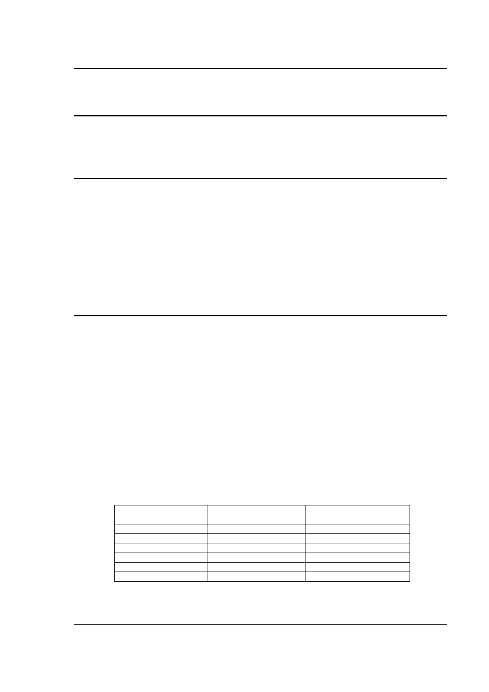
Set load switches for the resistance value shown in Table 6-1 for the CSW model to be
calibrated.
4.
Program the output to the maximum current value, Constant Current [CC] Mode, High Voltage
range, ALC OFF and 230.0 volts for all phases.
5.
Go the to the Current Measurement Calibration Menu. Enter the actual load current for phase
A as the variable. Determine the current value from the formula; I = V / Rshunt where V is the
voltage from the shunt.
6.
Repeat steps 1 through 4 for the Phase B and C outputs.
7.
Program the 1-phase mode of operation. Connect the Phase A, B and C outputs together.
8.
Repeat steps 1 through 4 for the 1-Phase mode of operation. Use the load value for the 1-
Phase mode shown in Table 6-1.
9.
Program the source and External DMM to the DC function. Repeat steps 2 through 8.
CSW Model
3-Phase
Load Value
1-Phase
Load Value
CSW5550
32.0 ohms
10.0 ohms
CSW11100
15.0 ohms
5.00 ohms
CSW16650
10.0 ohms
3.33 ohms
CSW22200
7.00 ohms
2.50 ohms
CSW27750
6.00 ohms
2.00 ohms
CSW33300
5.00 ohms
1.67 ohms
Table 5-1: Load Values for Output Current Calibration