AMETEK CSW Series User Manual
Page 105
User Manual
California Instruments
CSW Series
105
21. Move the cursor to the START field and press the ENTER key. The transient program you
just created will execute two times. If you have an oscilloscope connected to the output, you
may be able to see the output voltage change per Figure 3-46.
Note: The AC source output remains at the last programmed values at the completion of
the list.
In three-phase mode, the voltage lists are phase selectable. You can set up a different voltage
list for each phase. To do this, use the PHASE key to choose the desired phase, as described in
the example. Note that fields common to all phases such as DURATION, END DELAY and
REPEAT always apply to all three phases in three-phase mode. When the cursor is moved to
any of these fields, the phase enunciator in the top right-hand corner always reverts to øABC.
Frequency transients are identical to voltage transients except they apply to all three phases at
all times in a three-phase configuration.
3.16.6 Programming Slew Rates
As shown in the previous examples there are a number of ways that you can generate custom
waveforms. Programmable slew rates provide additional flexibility when customizing waveforms.
Slew rates determine how fast the voltage or frequency is changed by the controller when a
step, pulse, or list transient is triggered. Slew rates cannot be programmed from the front panel
and are always set to their maximum values at power on. To use programmable slew rates, the
AC source must be programmed over the bus. Refer to the SCPI Programming Manual for more
information about programming slew rates.
3.16.7 Switching Waveforms
The FUNCTION field available in each transient list event setup menu may be used to
dynamically switch waveforms during transient execution. This allows different waveforms to be
used during transient execution. Waveforms may be switched without the output of the source
being turned off. For three phase configurations, each phase has its own waveform list so
different waveforms may be programmed on different phases during transient execution.
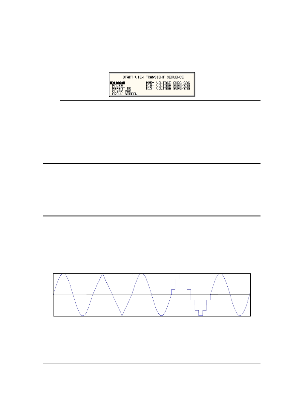
Figure 3-47 illustrates the concept of using different waveforms at different steps in a transient
list. In this case, the change was programmed to occur at the zero crossing. Any phase angle
can be used to start a transient step however.
Figure 3-47: Switching waveforms in a transient list