WaveWare Alert Utility User Manual
Page 25
Step 2 – Configuration – Output – LED Message Board(s)
To use LED Message Board(s) for an Output, you will need to Configure the Message Board(s) that will be used
with this Application. To Add a LED Message Board, Place a Check Mark next to “
LED Message Board(s)
” and
then Click on the “
Configure Message Board(s)
” Button. See Fig. 35
Fig. 35 LED Message Boards
Click on the “Configure Message Boards” Button
In the “Configure Message Board(s)” screen, you have these options:
There are Three Fields for Configuration for use with a LED Message Board(s):
Output Options
Message Display Configuration
Maintenance
Output Options:
For Reference, See Fig. 36
To use as a “
Wired Connection
”
o
Choose the Com Port that the LED Message Board is attached to and Configure the Port
To use as a “
Wireless Connection
” using a Paging Data Receiver, for Delivery of the Message to the Board(s)
o
This Option allows you to Send a Message to the Paging Data Receiver (PDR) that is attached to the
LED Message board(s), via the Paging System
To use “
Message Routing
”
o
This Option allows you to Associate a PIN Number to a Sign’s Address
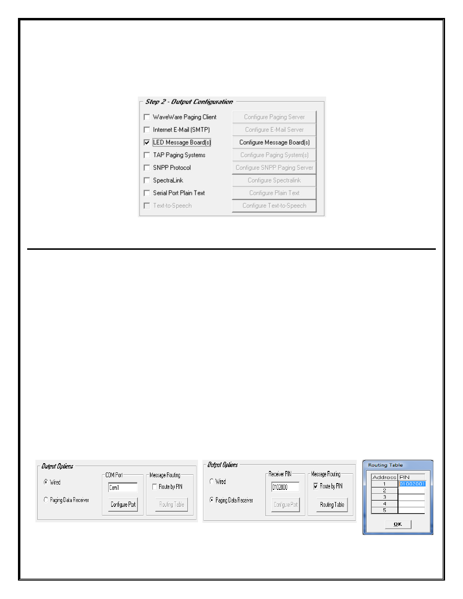
Wired - Configure Com Port
PDR–Configure PIN– Message Routing
Table
Fig. 36 Output Options
25