T*ap – Junger Audio T*AP Television Audio Processor Edition User Manual
Page 39
T*AP
35
setup GUI – AUDIO PROCESSOR – Input
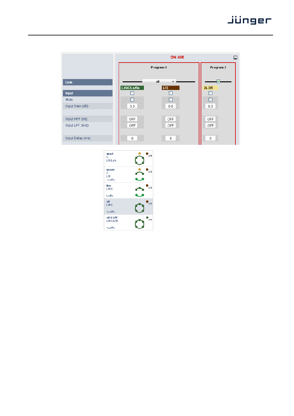
Link
defines the coupling of the control circuits in
order to maintain the listening balance for
correlated signals or to provide a grouping of
the setup parameters for multi channel
signals. To the left is an example that shows
the different link modes. This example
applies in general to all other link settings for
the T*AP.
Depending on the function block and the
control mode (ITU vs. EBU) the number of
possible link settings will differ.
Curves and dots of the same color indicate
the link condition.
Input
enables the control of the respective column
Mute
will mute all channels controlled by the respective column
Input Gain (dB)
sets the gain [-80 … +20]
Input HPF (Hz)
high pass filter (6dB/oct) cut off frequency [OFF, 2, 20, 40, 80, 120]
Input LPF (kHz)
low pass filter (6dB/oct) cut off frequency [OFF, 15, 20, 22]
Input Delay (ms)
[1 … 2000]