T*ap – Junger Audio T*AP Television Audio Processor Edition User Manual
Page 32
T*AP
28
setup GUI – ROUTING
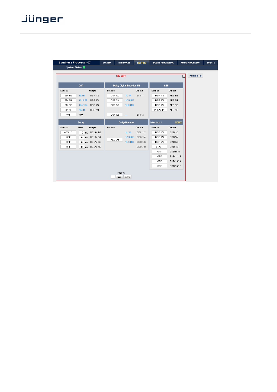
This is the core of the T*AP because it defines the audio signal flow inside the machine :
Each functional block of the device has an input- and an output-label. The output-labels are pre-defined,
while the label of an input must be selected by the administrator in order to route the signals.
Additional blue labels give an indication of the type of signal that is expected by the respective function block
input (e.g.
1L/1R
for the DSP). The labels depend on the Program Configuration.
The above screen shot shows an example configuration :
DSP
the de-embedder outputs [SDI 1/2 to 7/8] are connected to the
DSP 1/2 [
1L/1R
], 3/4 [
1C/1LFE
],
5/6
[1Ls/1Rs]
, 7/8 [
2L/2R
] inputs.
After processing by the DSP, these signals will leave it at the outputs
DSP 1/2 to 7/8.
Dolby Digital Encoder
an optional Dolby Digital encoder receives DSP 1/2 to 5/6 as an input,
while the 2
nd
encoder has DSP 7/8 assigned. After encoding the signals
appear at ENC 1 and ENC 2 outputs.
AES
the first three outputs AES 1/2 to AES 3/4 are connected with
DSP 1/2 to 5/6 (e.g. for monitoring purposes), while AES 7/8 is
connected to the delay output DELAY 1/2.
Delay
a signal pair from the AES 1/2 input will be delayed
by 85ms.
Dolby Decoder
an external signal from the 2nd AES input AES 3/4 will be decoded.
When the signal is present, the decoder reads the program
configurations and sets the labels [
1L/R
,
1C/LFE
,
1Ls/Rs
] accordingly
at the decoder outputs DEC 1/2, 3/4, 5/6.
Interface 1
DSP 1/2 … DSP 5/6 are connected with the embedder input
EMB 1/2 … EMB 5/6 while encoder output ENC 1 is connected with the
embedder input EMB 7/8. Where these signals will be embedded must
be defined on the respective setup pane :
INTERFACES > SDI I/O Interface > Embedder.