Locking pins – d&b V-Series User Manual
Page 12
2.5. Locking pins
WARNING!
Potential risk of personal injury and/or
damage to material!
The steel wires between the Locking pins of the cabinets and
rigging components are not intended to carry any load. The
cabinet's weight must only be carried by the Front and Splay/Rear
links in conjunction with the front and rear rigging strands of the
loudspeaker cabinets and the Flying frame.
Ensure all Locking pins are fully inserted and securely locked
before lifting any load.
The V-Series loudspeaker cabinets and flying frame are equipped
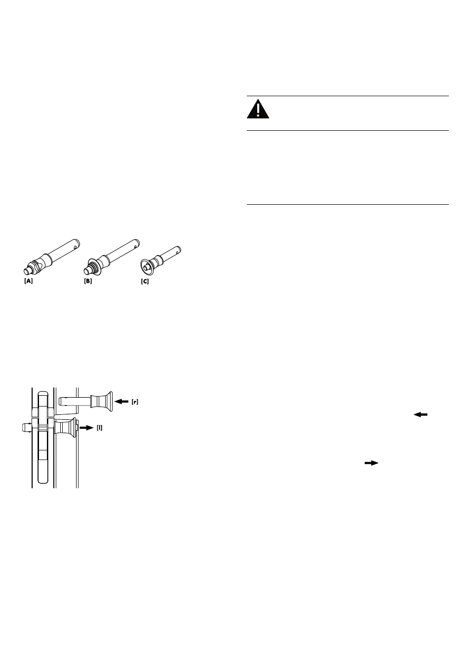
with three types of Locking pins:
Type [A]
Locking pin 10 x 35 mm.
Used for the Load adapters.
Type [B]
Locking pin 9 x 40 mm.
Used for the cabinets' Splay/Rear links and for the
frame's Splay link and Cable pick.
Type [C]
Locking pin 8 x 23 mm.
Used for the Front links of the loudspeaker cabinets
and the frame.
Note: The Locking pins are undetachably attached to the
different rigging components on the cabinet and the frame
using steel wires.
Throughout this manual these steel wires are not shown in the
corresponding illustrations.
Functionality (Quick lock mechanism)
The quick lock mechanism applies to all types of Locking pins listed
above. Proceed as follows:
1. Press the button to
release the locking mechanism (
[r]).
2. Remove the Locking pin through the respective link or socket.
3. Insert the Locking pin through the respective link or socket until
it is fixed in place.
4. Release the button to
lock the pin (
[l]).
5. Recheck the Locking pin is securely locked by briefly pulling
the Locking pin towards you.
Locking pin assembly
Shown with pin type
[C]
d&b V-Series Rigging manual (1.9 EN)
12