Altera Arria V SoC User Manual
Page 13
Chapter 3: Board Setup and Defaults
3–3
Factory Default Switch and Jumper Settings
June 2014
Altera Corporation
Arria V SoC Development Kit
User Guide
To restore the switches to their factory default settings, perform these steps:
1. Set the DIP switch bank (SW2) to match
and
.
In the following table, ON indicates the switch is to the left according to the board
orientation as shown in
.
2. Set the DIP switch bank (SW3) to match
and
.
In the following table, up and down indicates the position of the switch with the
board orientation as shown in
Important: The default MSEL pin settings are set to all zeroes (ON) to select the fast
passive parallel x16 mode. For power-up configuration from MAX V and CFI
flash, ensure that the MAX V design uses this same mode as does in the design in
the
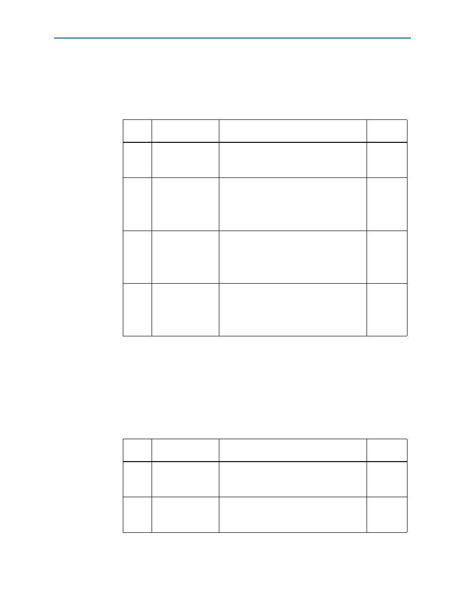
Table 3–1. SW2 DIP Switch Settings
Switch
Board
Label
Function
Default
Position
1
CLK125A
Switch 1 has the following options:
■
ON (0) = On-board oscillator is disabled.
■
OFF (1) = On-board oscillator is enabled.
OFF
2
Si570
Switch 2 has the following options:
■
ON (0) = On-board programmable oscillator is
enabled.
■
OFF (1) = On-board programmable oscillator is
disabled.
ON
3
FACT LOAD
Switch 3 has the following options:
■
ON (0) = Load the user design from flash at
power up.
■
OFF (1) = Load the user factory from flash at
power up.
OFF
4
Security
Switch 4 has the following options:
■
ON (0) = On-Board USB Blaster II sends
FACTORY command at power up
■
OFF (1) = On-Board USB Blaster II does not
send FACTORY command at power up
OFF
Table 3–2. SW3 DIP Switch Settings (Part 1 of 2)
Switch
Board
Label
Function
Default
Position
1
MSEL0
Switch 1 has the following options:
■
ON (up) = MSEL0 is 0.
■
OFF (down) = MSEL0 is 1.
ON
2
MSEL1
Switch 2 has the following options:
■
ON (up) = MSEL1 is 0.
■
OFF (down) = MSEL1 is 1.
ON