Pilz PSS67 F 16DI SB-T User Manual
Page 43
9 - 3
Operating Manual: PSS67 F 16DI SB-T
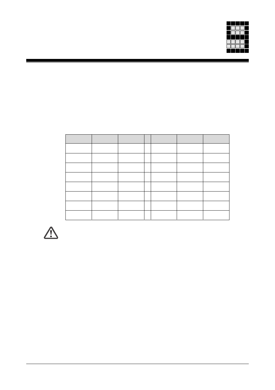
Example: Device address is 36
Input
Section Address
Input
Section Address
I
0
A
E36.00
I
8
A
E36.08
I
1
A
E36.01
I
9
A
E36.09
I
2
B
E36.18
I
10
A
E36.10
I
3
B
E36.19
I
11
A
E36.11
I
4
B
E36.20
I
12
A
E36.12
I
5
A
E36.05
I
13
B
E36.29
I
6
A
E36.06
I
14
B
E36.30
I
7
A
E36.07
I
15
B
E36.31
WARNING!
Any errors made when setting the device address will result in the loss of
the safety function.
If the same device address is set on two modules or the device addresses
of two modules are transposed, the controlling PSS may unknowingly
address the wrong inputs/outputs.
This will cause the plant to malfunction. The safe operation of the plant is
no longer guaranteed.
To avoid this, the greatest possible care must be taken when setting the
device addresses.
The device address may not be modified while the module is being
operated on SafetyBUS p (“SB active” LED lights up green or flashes),
otherwise all the I/O-Groups configured on the module will switch to a
STOP condition.
If it is necessary to change the set device address while the bus is running,
you will need to disconnect the module from SafetyBUS p while you make
the change. When you re-establish the connection to SafetyBUS p, the
module will quickly be ready for operation again (“Device” LED lights up
green).
0 ... 15. The inputs from Section B are addressed under the device address
as slot number and bit number 16 ... 31; this corresponds to an offset of 16
in the bit number.
So if input I
6
from Section A is reconfigured into Section B, for example, the
address will change from x.06 to x.22.