Setting the device address, Operation and maintenance – Pilz PSS67 F 16DI SB-T User Manual
Page 42
Operation and Maintenance
9 - 2
Operating Manual: PSS67 F 16DI SB-T
Setting the device address
In order to operate the module on SafetyBUS p you will need to set the
device address that was defined for the module in the system software’s
configurator.
To do this you will need to use a screwdriver to open the transparent cover
on the rotary switches.
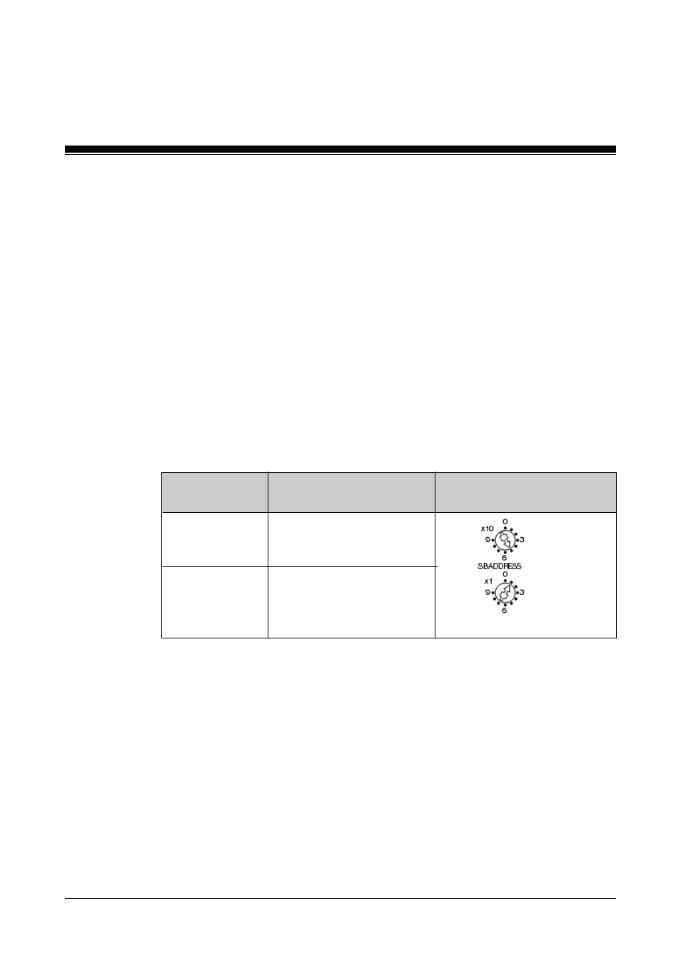
Use the rotary switches to set the required address. The rotary switch
labelled “x1” is used to set the units and the rotary switch labelled “x10” is
used to set the tens.
Permitted device addresses are in the range 32D ... 95D. The same applies
if the module is configured for SafetyBUS p 1 in the
SafetyBUS p Configurator on the PSS WIN-PRO system software. The
offset of 100D for device addresses on SafetyBUS p 1 is calculated
automatically from the bus configuration.
The I/O-Groups to which the module belongs must also be defined in the
system software’s configurator.
The module can be divided into sections A and B for this purpose. Section
A and section B may belong to different I/O-Groups. The module may either
have section A alone, section B alone, or both section A and section B. The
inputs can be assigned to both sections at will.
Membership of section A or section B is used in conjunction with the
device address to form the addresses under which the inputs can be
addressed by the controlling PSS.
In the process image of the controlling PSS, the inputs from Section A are
addressed under the device address as slot number and bit number
Rotary switch
"SB Address"
x10
x1
Example:
Device address 51D
Key
Set the tens
Set the unit