Incremental encoder operating mode, 4function description, 1 module features – Pilz PSSu E S INC User Manual
Page 19: 3 incremental encoder operating mode
Pilz GmbH & Co. KG, Felix-Wankel-Straße 2, 73760 Ostfildern, Germany
Telephone: +49 711 3409-0, Telefax: +49 711 3409-133, E-Mail: [email protected]
4-3
4.1
Module features
4
Function description
4.1.3
Incremental encoder operating mode
Incremental encoder operating mode
4-
][Funktionsbeschreibung_Ein ST-INC BA
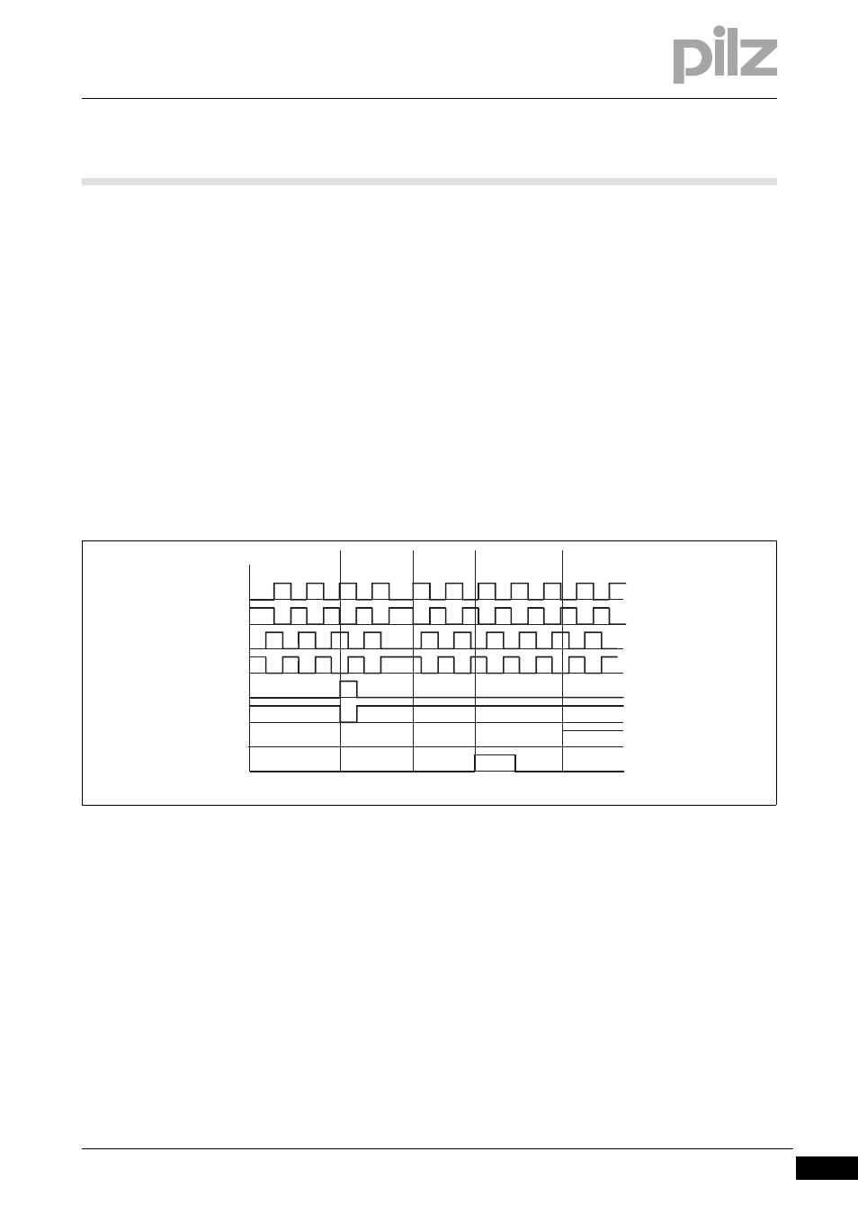
The counter outputs and the output for the incremental encoder's zero
pulse are connected to the dual-pole inputs (A, B, C).
Inputs A, B
The first channel of the encoder is connected to input A, the second
to input B. The second channel is 90° out of phase. If channel A is
leading, the module counts forwards. If channel A is lagging, the mod-
ule counts backwards (see timing diagram).
Input C
The output for the incremental encoder's zero pulse is connected to
input C. An incremental encoder typically supplies one zero pulse per
rotation. If the zero pulse function is activated, the module copies the
last value prior to the zero pulse into the latch memory and passes it
to the process image of inputs (see chapter entitled "Transfer counter
status via latch pulse").
Key:
a: The counter counts backwards because the signal at channel A is
lagging.
b: The module has received a zero pulse. Provided the function is ac-
tivated, the counter value is copied into the latch memory with a rising
edge at input C+.
c: The counter counts forwards because the signal at channel A is
leading.
d: The module has received a latch pulse. Provided the function is ac-
tivated, the counter value is copied into the latch memory with a rising
edge at input L.
e: The counter is disabled because there is a 1 signal at input G.
][Funktionsbeschreibung_Ein ST-INC BA vielfach
C+
G
L
C-
a
b
c
d
e
B+
B-
A+
A-