Pilz PNOZmc5.1p Interbus LWL / Fiberoptic User Manual
Page 2
- 2 -
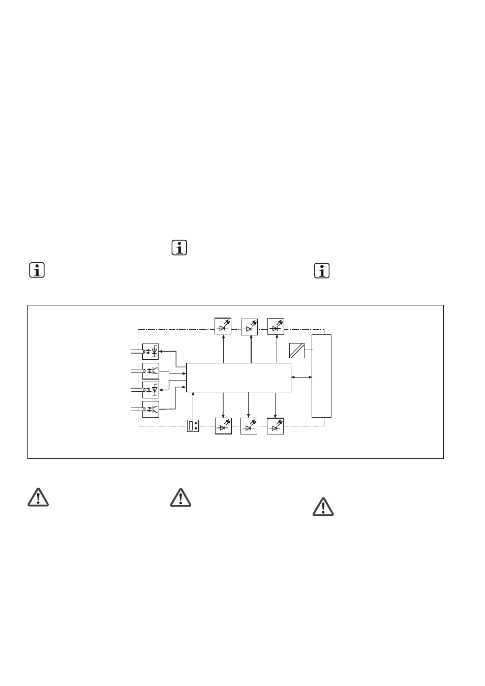
Innenschaltbild
Internal wiring diagram
Schéma interne
Modulmerkmale:
• konfigurierbar mit PNOZmulti Configurator
• Übertragungsrate wählbar zwischen
500 kBit/s oder 2 MBit/s
• Statusanzeigen für Kommunikation mit
dem INTERBUS LWL und von Fehlern
• F-SMA-Schraubanschlüsse für LWL-Kabel
Funktionsbeschreibung
Arbeitsweise:
Die über den INTERBUS LWL zu übertra-
genden Daten werden im PNOZmulti
Configurator ausgewählt und konfiguriert.
Die Verbindung zwischen Basisgerät und
dem PNOZ mc5.1p erfolgt über eine
Steckbrücke. Über diese Steckbrücke wird
das PNOZ mc5.1p auch mit Spannung
versorgt. Nach Einschalten der
Versorgungsspannung oder einem Reset des
Sicherheitssystems PNOZmulti wird das
PNOZ mc5.1p automatisch konfiguriert und
gestartet.
Funktionen:
LEDs zeigen den Status des Erweiterungs-
moduls PNOZ mc5.1p am INTERBUS LWL
an.
INFO
In der Online-Hilfe des PNOZmulti
Configurators ist die Konfiguration
des PNOZ mc5.1p ausführlich
beschrieben.
PNOZ mc5.1p montieren
Beachten Sie bei der Montage:
Achtung! Durch elektrostatische
Entladung können Bauteile der
Sicherheitssteuerung beschädigt
werden. Sorgen Sie für Entladung,
bevor Sie die Sicherheitssteuerung
berühren, z. B. durch Berühren einer
geerdeten, leitfähigen Fläche oder
durch Tragen eines geerdeten
Armbands.
• Montieren Sie das Sicherheitssystem in
einen Schaltschrank mit einer Schutzart
von mindestens IP54.
• Montieren Sie das Sicherheitssystem auf
eine waagrechte Tragschiene. Die
Lüftungsschlitze müssen nach oben und
unten zeigen (siehe Betriebsanleitung des
Basisgeräts PNOZ m0p, PNOZ m1p,
PNOZ m2p). Andere Einbaulagen können
zur Zerstörung des Sicherheitssystems
führen.
• Befestigen Sie das Sicherheitssystem mit
Hilfe der Rastelemente auf der Rückseite
Module features:
• Can be configured using the PNOZmulti
Configurator
• Transmission rate, selectable between
500 kBit/s and 2 MBit/s
• Status indicators for communication with
INTERBUS FO and for errors
• F-SMA screw connections for FO cable
Function description
Operation:
The data to be transferred via the
INTERBUS FO are selected and configured
in the PNOZmulti Configurator.
The base unit and the PNOZ mc5.1p are
connected via a jumper. The PNOZ mc5.1p
is also supplied with voltage via this jumper.
After the supply voltage is switched on or the
PNOZmulti safety system is reset, the PNOZ
mc5.1p is configured and started automati-
cally.
Functions:
LEDs indicate the status of the PNOZ mc5.1p
expansion module on the INTERBUS FO.
INFORMATION
The configuration of the PNOZ mc5.1p
is described in detail in the
PNOZmulti Configurator’s online help.
Installing the PNOZ mc5.1p
Please note for installation:
Caution! Electrostatic discharge can
damage components on the safety
system. Ensure discharge before
touching the safety system, e.g. by
touching an earthed, conductive
surface or by wearing an earthed
armband.
• The safety system should be installed in a
control cabinet with a protection type of at
least IP54.
• Fit the safety system to a horizontal DIN
rail. The venting slots must point up and
down (see operating instructions for the
PNOZ m0p, PNOZ m1p and PNOZ m2p
base units). Other mounting positions
could damage the safety system.
• Use the notches on the rear of the safety
system to attach it to a DIN rail. Connect
the safety system to the DIN rail in an
upright position so that the earthing
springs on the safety system are pressed
on to the DIN rail.
Caractéristiques du module :
• Paramétrable avec le configurateur
PNOZmulti
• Vitesse de transmission de 500 kBit/s ou
2 MBit/s au choix
• Affichage d’état pour la communication
avec le bus INTERBUS à fibres optiques
et pour les erreurs
• Raccordements par vis F-SMA pour câbles
à fibres optiques
Descriptif du fonctionnement
Mode de travail :
Les données à transmettre par le bus
INTERBUS à fibres optiques sont sélection-
nées et configurées dans le configurateur
PNOZmulti.
Le raccordement entre l’appareil de base et le
PNOZ mc5.1p est réalisé au moyen d’un pont
enfichable. Celui-ci assure également
l’alimentation du PNOZ mc5.1p. Après
application de la tension d’alimentation ou
réinitialisation du système de sécurité
PNOZmulti, le module PNOZ mc5.1p est
automatiquement configuré et démarré.
Fonctions :
Les LED indiquent l’état du module d’exten-
sion PNOZ mc5.1p sur le bus INTERBUS à
fibres optiques.
INFORMATION
La configuration du module
PNOZ mc5.1p est décrite en détail
dans l’aide en ligne du configurateur
PNOZmulti.
Installer le PNOZ mc5.1p
Pour le montage, respectez les consignes
suivantes :
Attention ! Une décharge électrosta-
tique peut endommager les éléments
de l’automate de sécurité. Veillez à
vous décharger avant de toucher
l’automate de sécurité, par ex. en
touchant une surface conductrice
mise à la terre ou en portant un
bracelet de mise à la terre.
• Montez le système de sécurité dans une
armoire d’indice de protection IP 54 au
moins.
• Montez le système de sécurité sur un
profilé support horizontal. Les ouïes de
ventilation doivent être orientées vers le
haut et vers le bas (voir le manuel d’utili-
sation de l’appareil de base PNOZ m0p,
PNOZ m1p, PNOZ m2p). D’autres
positions de montage peuvent entraîner la
destruction du système de sécurité.
• Montez le système de sécurité sur un rail
DIN à l’aide du système de fixation situé
PNOZ m1p
500k
2M
CC/RC
RD
BA
IBS OUT
DC
DC
Controller
TX
RX
RX
FO1
TR
FO2
IBS IN
TX