4 function description, 1 device properties, 1 integrated protection mechanisms – Pilz PNOZ mm0p-T User Manual
Page 12: 2 operation, 3 block diagram, 4 diagnostics, Section 4, Function description, Device properties, Integrated protection mechanisms
Function description
Operating Manual PNOZ mm0p-T
1002704-EN-01
12
Function description
Device properties
Integrated protection mechanisms
The relay conforms to the following safety criteria:
}
The circuit is redundant with built-in self-monitoring.
}
The safety function remains effective in the case of a component failure.
}
The safety outputs are tested periodically using a disconnection test.
Operation
The function of the safety system's inputs and outputs depends on the safety circuit created
using the PNOZmulti Configurator. A chip card is used to download the safety circuit to the
base unit. The base unit has 2 microcontrollers that monitor each other. They evaluate the
input circuits and switch the outputs accordingly.
The LEDs indicate the status of the safety system plus the inputs and outputs.
The online help on the PNOZmulti Configurator contains descriptions of the operating
modes and all the functions of the PNOZmulti safety system, plus connection examples.
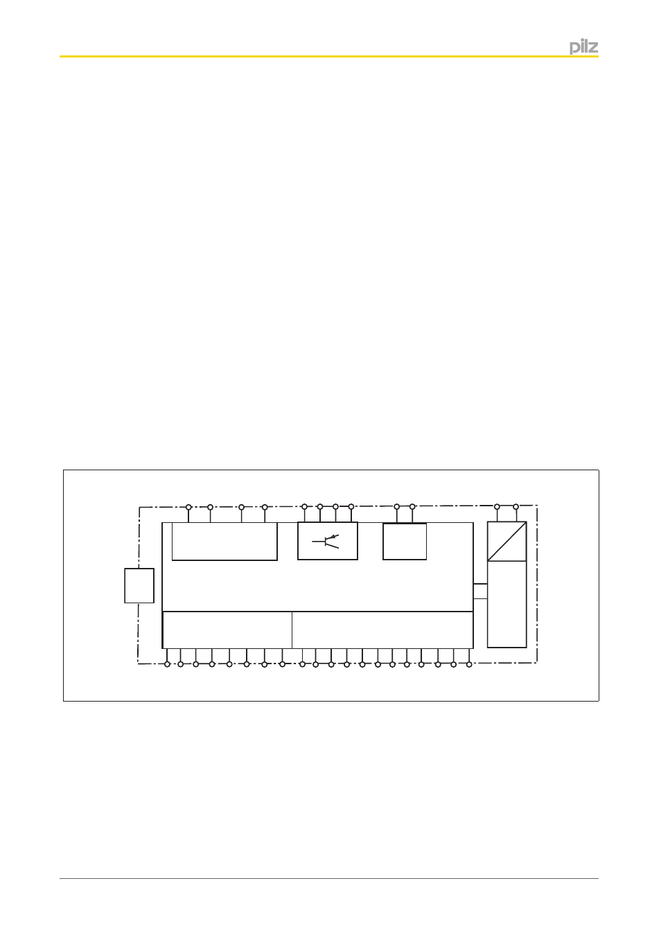
Block diagram
=
Power
A1 A2
=
Input
US
B
IM1
I8
I5
I11
I4
I9
I12 I13 I14 I15
I7
I6
I10
IM2
IM0
IM3 IM16
IM18
IM17
IM19
Configurable
input/output
Configurable
output
24 V 0 V
T1M21
O2
O0 O1
O3
T2M22 T3M23
T0M20
24 V 0 V
Diagnostics
The status and error messages displayed by the LEDs are saved in an error stack. This
error stack can be read out from PNOZmulti Configurator via the USB interface.
4
4.1
4.1.1
4.1.2
4.1.3
4.1.4