Block diagram/terminal configuration, Function description, Installation – Pilz PZE X4V 0,5/24VDC 4n/o fix User Manual
Page 6: Pze x4v
PZE X4V
Operating Manual PZE X4V
1003200EN08
6
}
Earth fault in the feedback loop:
Detected, depending on the base unit that is used.
}
Earth fault in the input circuit:
The output relays deenergise and the safety contacts open.
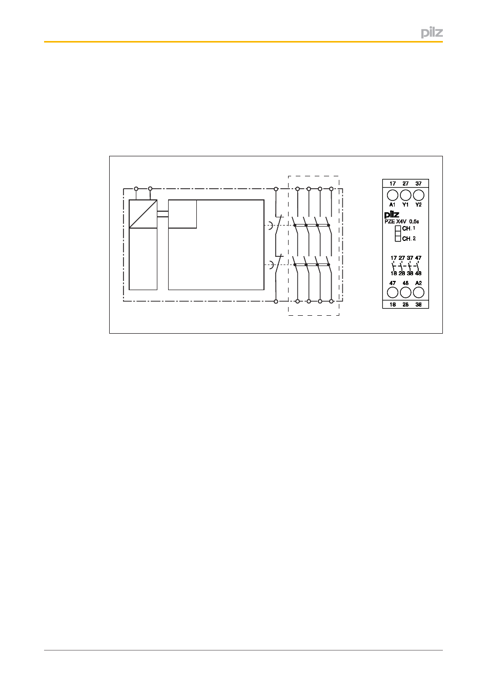
Block diagram/terminal configuration
=
=
Power
K1
Input
A1
A2
17 27 37
Y1
18 28 38
Y2
47
48
K2
*
CH.
CH.
A2
47
48
38
28
18
Y2
A1
Y1
37
17
27
48
38
18 28
37
17 27
47
CH
CH
CH
CH
CH
CH
CH
.
..
.
.
.
.
CH
CH
CH
CH
CH
CH
CH
.
..
.
.
.
.
A2
A2
A2
A2
A2
A2
A2
47
47
47
47
47
47
47
48
48
48
48
48
48
48
38
38
38
38
38
38
38
28
28
28
28
28
28
28
18
18
18
18
18
18
18
Y2
Y2
Y2
Y2
Y2
Y2
Y2
A1
A1
A1
A1
A1
A1
A1
Y1
Y1
Y1
Y1
Y1
Y1
Y1
37
37
37
37
37
37
37
17
17
17
17
17
17
17
27
27
27
27
27
27
27
48
48
48
48
48
48
48
38
38
38
38
38
38
38
18
18
18
18
18
18
18
28
28
28
28
28
28
28
37
37
37
37
37
37
37
17
17
17
17
17
17
17
27
27
27
27
27
27
27
47
47
47
47
47
47
47
PZE X4V 0,5s
PZE X4V 0,5s
PZE X4V 0,5s
PZE X4V 0,5s
PZE X4V 0,5s
PZE X4V 0,5s
PZE X4V 0,5s
1
1
1
1
1
1
1
2
2
2
2
2
2
2
*Insulation between the nonmarked area and the relay contacts: Basic insulation (over
voltage category III), Protective separation (overvoltage category II)
Function description
The contact expansion module is an addon device with delayon deenergisation, and it is
used to expand a safety circuit. The contact expansion module is driven by a base unit (e.
g. emergency stop relay).
}
Functional procedure after closing the safety contacts of the base unit:
–
The supply voltage is present at the input (A1) of the contact expansion module.
–
Close the safety contacts 1718, 2728, 3738 and 4748.
–
The LEDs "CH. 1" and "CH. 2" are lit.
}
Functional procedure after opening the safety contacts of the base unit:
–
There is not supply voltage at input (A1) of the contact expansion module.
–
Safety contacts 1718, 2728, 3738 and 4748 open after the delay time.
–
The LEDs "CH. 1" and "CH. 2" go out.
Installation
}
The unit should be installed in a control cabinet with a protection type of at least IP54.
}
Use the notch on the rear of the unit to attach it to a DIN rail.
}
Ensure the unit is mounted securely on a vertical DIN rail (35 mm) by using a fixing ele
ment (e.g. retaining bracket or an end angle).