Raid channel configurations, Typical raid channel configurations – StorCase Technology SCSI-to-SCSI Single RAID User Manual
Page 16
6
Installation
StorCase Technology, Inc.
DXIFS-160/RAID User's Guide - Rev. B00
RAID CHANNEL CONFIGURATIONS
NOTE:
The installation, configuration, and use of the InfoStation RAID Controller
Module requires a certain level of expertise and experience on the part
of the user/integrator. Since there are many configuration options and
variables (ie. host platforms, applications, etc.), only general guidelines
will be discussed in this User's Guide.
CAUTION:
Offset VHDCI cable connectors must be used for proper fit. Failure to use
proper cables may result in damage to the I/O VHDCI connectors on the
InfoStation I/O repeater modules and RAID Controller Module! RAID Con-
troller "Kits" containing external I/O cables are available; contact StorCase
for further ordering information.
Typical RAID Channel Configurations
NOTE:
StorCase recommends the use of Port A-1 & A-2 when configuring typical RAID
channels (as shown in Figures 3, 4 & 5A). In the special cases where extra length
cables are required (up to 12m maximum), use Port B instead (Figure 5B).
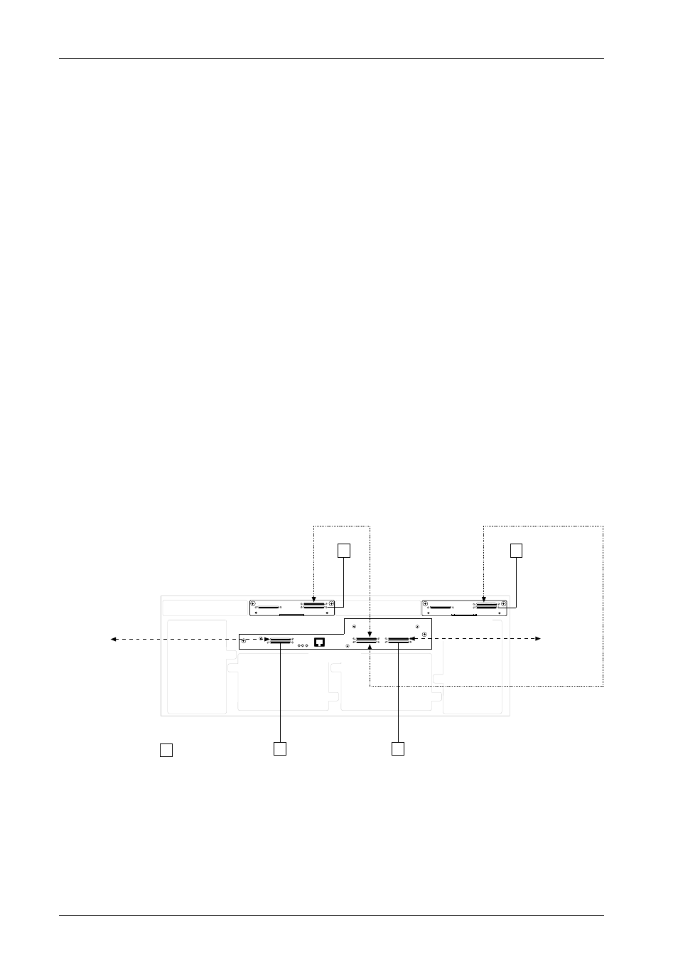
IFS_RAID21
Disk Ch. 1
(4 Disks)
Disk Ch. 2
(5 Disks)
To Host 0
To Host 1
I/O Repeater
Module #2
I/O Repeater
Module #1
RAID Module
T
T
T
T
T
=Terminator
Figure 3: Typical InfoStation RAID Module 2x2 Dual-Channel Configuration
(Single InfoStationChassis)