Infostation raid controller module panel – StorCase Technology SCSI-to-SCSI Single RAID User Manual
Page 14
4
Introduction
StorCase Technology, Inc.
DXIFS-160/RAID User's Guide - Rev. B00
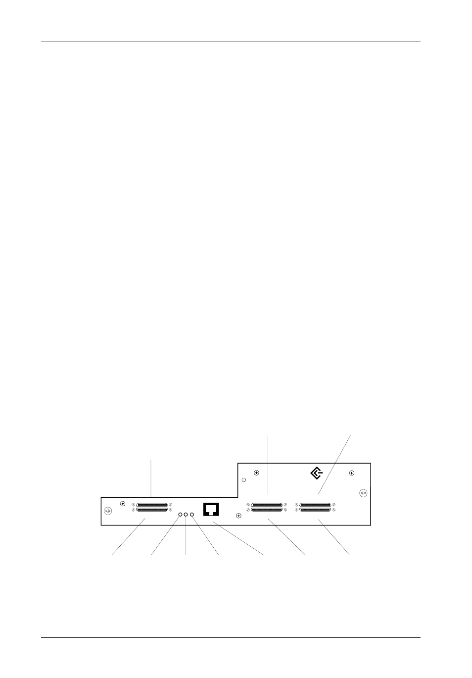
Figure 2: RAID Controller Module Panel
InfoStation RAID Controller Module Panel
(Figure 2)
Host Channel 0 (In) - Connects to SCSI Host 0
Host Channel 0 (Out) - Connects to LVD/S.E. Multi-mode terminator (or other SCSI
device)
Host Channel 1 (In) - Connects to SCSI Host 1
Host Channel 1 (Out) - Connects to LVD/S.E. Multi-mode terminator (or other SCSI
device)
Disk Channel 1 - Connects to InfoStation I/O repeater module #1
Disk Channel 2 - Connects to InfoStation I/O repeater module #2
SCSI Host Activity - Provides a visual indication of host activity.
Error LED - Provides a visual indication of error conditions
Cache Backup LED - Provides the following information:
ON
= Indicates that data is in Cache Memory
OFF
= Indicates that data write to disk is complete
RS-232 Serial Port (RAID Configuration Port) - Connects to a VT-100/ANSI terminal
via an RJ45-DB9 cable (provided). Refer to page 11 - section "Configuration" for
further information.
Host Channel 0
(In)
Host Channel 1
(In)
Disk
Channel 2
Disk
Channel 1
RS-232
Serial Port
Cache
Backup
LED
Error
LED
SCSI
Host Activity
LED
Host Channel 1
(Out)
Host Channel 0
(Out)
IFS_41
DISK CH. 2
DISK CH. 1
HOST 0 (IN)
HOST 0 (OUT)
HOST 1 (IN)
HOST 1 (OUT)
RS-232
ACTIVITY
ERROR
CACHE
SCSI
LVD/SE
ULTRA160