HITEC Optic 6 User Manual
Page 5
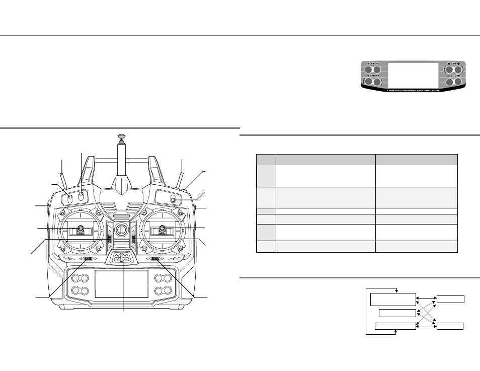
Transmitter Input Buttons
Optic Controls and Switch Assignments
Receiver - Servo Connection List
Transmitter Displays and Messages
Factory Repair Service Information
Please read the warranty card supplied with your system and
return it. Before you decide to have your system repaired, if
there is no apparent physical damage, read this instruction
manual again and check to be sure that you are operating the
system as it was designed to be operated. If you are still
having trouble, pack up your system in its original shipping
materials and send it to the nearest authorized Hitec R/C
Service Center.
Be sure to include a note in your package that describes the
trouble in as much detail as possible, including:
- Symptoms of the problem in as much detail as you can
provide, including any unusual mounting conditions or
equipment orientation
- A list of items you are sending, and what you want to be
repaired.
- Your name, address, and telephone number.
The buttons are used for different things as follows:
1. The Edit buttons allow you to move up and down within the
model menus, and move within the regular display.
2. The Cursor Left/Right buttons allow you to select options
within a particular function, and control the timer function.
3. The Data +Increase & -Decrease buttons allow you to
increase or decrease the numerical settings for a function
4. The Clear Active/Inhibit button resets numbers, and turns
functions on and off.
5. The Lock button holds the throttle channel fixed while other
channels still respond to the transmitter.
You'll learn how to use these buttons in the setup sections that follow.
When you first turn on your transmitter, the first screen shown
below appears on the LCD display. Before flying, or even
starting the engine, BE SURE that the model number
appearing in the upper right of the display matches the
model that you are about to fly! If you don't, reversed
servos and incorrect trims will lead to an immediate crash.
You can scroll up and down through the startup screen by
pressing one of the two Edit keys (the two keys on the far left).
If you press timer or engine cut or lock keys, you go directly to
those functions regardless of the display.
The table below shows the hookups that should be used for each of the model types. Note that some functions shown will not
operate until they are activated in the transmitter.
The servo response varies with the selected function. Standard options are shown first.
Web site: http://www.hitecrcd.com
Hitec-RCD, Inc.
12115 Paine St.
Poway, CA 92064
Telephone: 1-858-748-6948
FAX 1-858-748-1767
This figure shows the assignments for a Mode 2 system as supplied by the factory in North America.
Note that some of the functions will not operate until activated in the mixing menus.
Receiver
channel
1
2
3
4
5
6
Aircraft Glider
(ACGL)
Aileron
or Right flaperon (FLPN on)
or Right elevon (ELVN on)
or Right aileron (ADIF on)
Elevator
or V-tail right side (VTAL on)
or Left Elevon (ELVN on)
or Right elevator (AILV on)
Throttle (controlled by throttle stick or Switch 01)
Rudder or
V-tail left side (VTAL on)
Landing gear (controlled by Gear/Aux switch)
or Left aileron (ADIF on)
or Left elevator (AILV on)
Flap (travel controlled by VR-L and neutral set by VR-R)
or Left flaperon (FLPN on)
Helicopter
(HELI)
Aileron (or Roll Cyclic)
or Swash servo 1 (120')
Elevator (or Pitch Cyclic)
or Swash servo 2 (120')
Throttle
Rudder
(Or Yaw control through the gyro)
Gyro sensitivity
(values set in GYRO menu)
Pitch (or Collective)
or Swash servo 3 (120')
Voltage/Timer Display
Normal Display Mode
Timer Display
Trim Menu [TRIM]
Model Name Display
Throttle Lock
+ DATA key
- DATA key
Edit keys
Edit keys
Lock key
Transmitter Input Buttons, Receiver - Servo Connection List, Receiver - Servo Connection List - Page 9
Factory Repair Service Information, Optic Controls and Switch Assignments - Page 8
1
2
2
1
3
5
4
3
Trainer Switch
Engine Cut
Switch
SW 3
Aileron Dual
Rate Switch
Right Lever
SW 1
Elevator-Rudder
Dual Rate Switch
Left Lever
Rudder -
Throttle Stick
Aileron &
Elevator Stick
Throttle
Trim Switch
Elevator
Trim Switch
Rudder
Trim Switch
Aileron
Trim Switch
Power Switch
SW 2
Gear or
Auxiliary Switch
SW 4
Flight Mode
Switch